shredder929
Junior Member level 3
- Joined
- Jul 1, 2019
- Messages
- 27
- Helped
- 1
- Reputation
- 2
- Reaction score
- 2
- Trophy points
- 3
- Location
- Massachusetts
- Activity points
- 408
Hi everyone,
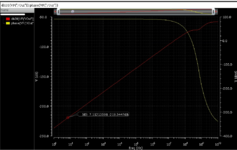
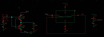
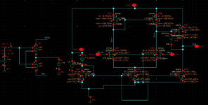
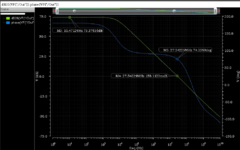
This is my first time designing an op amp, using 180nm in Cadence. Two stage design, 1st stage is NMOS differential pair with PMOS current mirror load, second stage is PMOS CS with Miller capacitor. Pictures attached are the DC operating points of the circuit, open loop gain, the closed loop test bench, and unity closed loop gain.
I have 1V common going into both inputs for the open loop. The current source is set to 20uA, the Vdd is 1.8V.
As you can see from the graphs, the gain is 73dB in open loop, which should be high enough, and the gain margin is great. At DC, the output is nearly Vdd/2, so that should be okay. Now all I've done is connect the output back to the input, which should give me a gain of 0dB or close to it, and instead I am getting baffling gains of -200dB or -400dB. The output seems to immediately saturate to one of the rails when I look at a transient simulation.
Am I just running the testbench wrong? It feels like it should be very simple and that I'm making some simulation mistake that's causing a convergence error or something in Cadence. Any insight or help appreciated, let me know if you need more details from me.
Found my answer. I took a hard look at it and followed the feedback path, figuring out how the voltage at each node changes depending on if the input goes up or down.
Turns out I was setting it in positive feedback. My diff pair's single ended *positive* output gets inverted by the CS stage. So in fact when I look at the op-amp as a whole, the negative input of the differential pair becomes the positive input of the whole op-amp.
Problem solved. Check your polarities!
This is my first time designing an op amp, using 180nm in Cadence. Two stage design, 1st stage is NMOS differential pair with PMOS current mirror load, second stage is PMOS CS with Miller capacitor. Pictures attached are the DC operating points of the circuit, open loop gain, the closed loop test bench, and unity closed loop gain.
I have 1V common going into both inputs for the open loop. The current source is set to 20uA, the Vdd is 1.8V.
As you can see from the graphs, the gain is 73dB in open loop, which should be high enough, and the gain margin is great. At DC, the output is nearly Vdd/2, so that should be okay. Now all I've done is connect the output back to the input, which should give me a gain of 0dB or close to it, and instead I am getting baffling gains of -200dB or -400dB. The output seems to immediately saturate to one of the rails when I look at a transient simulation.
Am I just running the testbench wrong? It feels like it should be very simple and that I'm making some simulation mistake that's causing a convergence error or something in Cadence. Any insight or help appreciated, let me know if you need more details from me.
--- Updated ---
Found my answer. I took a hard look at it and followed the feedback path, figuring out how the voltage at each node changes depending on if the input goes up or down.
Turns out I was setting it in positive feedback. My diff pair's single ended *positive* output gets inverted by the CS stage. So in fact when I look at the op-amp as a whole, the negative input of the differential pair becomes the positive input of the whole op-amp.
Problem solved. Check your polarities!
Attachments
Last edited: