sdowney717
Member level 1
I am not even sure how to ask the question, but I will describe.
This Onan has an auto start and stop feature.
Works great except the off part does not turn off if an AC device is still drawing power. Which is what you want.
But it is the setting thresh hold for the off I want to modify.
I added two AC digital gauges with AC volts and AC amps and apparently they draw enough power to keep the gen running.
I want to adjust it so it shuts off even if those AC digital gauges are in circuit.
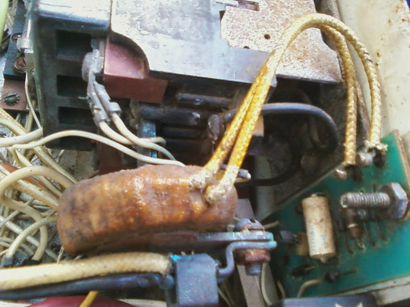
Here is the Onan AC current sensing coil. If gen is on manually, I measured the coil with nothing hooked up at 0.04 vac
If the gauges run, the coil output reads 1.9 vac
If I run something that draws 10 amps, the AC coil reads 4 vac.
So I imagine the circuit board, if the vac or maybe amps coming out of this coil goes below a certain amount, the circuit board turns the gen to off.
here are pics of the coil and the small circuit board. The circuit board when gen is off but set to auto start if a load is detected, sends 12 vdc signal onto the ac wires. When a load of maybe 10 or 20 watts is turned on, the circuit board turns on the gen. The turn off feature is controlled by this big wire coil around the AC output wire.

circuit board to right, sense coil to left
would adding a resistor in series with this coil do anything about this?
I have the circuit diagram will post in a few minutes
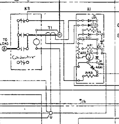
ok here are 2 screens of that circuit board from the manual
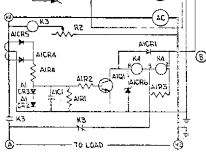
T1 is that sense coil
Transistor is an NTE199
This Onan has an auto start and stop feature.
Works great except the off part does not turn off if an AC device is still drawing power. Which is what you want.
But it is the setting thresh hold for the off I want to modify.
I added two AC digital gauges with AC volts and AC amps and apparently they draw enough power to keep the gen running.
I want to adjust it so it shuts off even if those AC digital gauges are in circuit.
Here is the Onan AC current sensing coil. If gen is on manually, I measured the coil with nothing hooked up at 0.04 vac
If the gauges run, the coil output reads 1.9 vac
If I run something that draws 10 amps, the AC coil reads 4 vac.
So I imagine the circuit board, if the vac or maybe amps coming out of this coil goes below a certain amount, the circuit board turns the gen to off.
here are pics of the coil and the small circuit board. The circuit board when gen is off but set to auto start if a load is detected, sends 12 vdc signal onto the ac wires. When a load of maybe 10 or 20 watts is turned on, the circuit board turns on the gen. The turn off feature is controlled by this big wire coil around the AC output wire.
circuit board to right, sense coil to left
would adding a resistor in series with this coil do anything about this?
I have the circuit diagram will post in a few minutes
ok here are 2 screens of that circuit board from the manual
T1 is that sense coil
Transistor is an NTE199
Last edited: