barry3223
Newbie level 1
Hi y'all
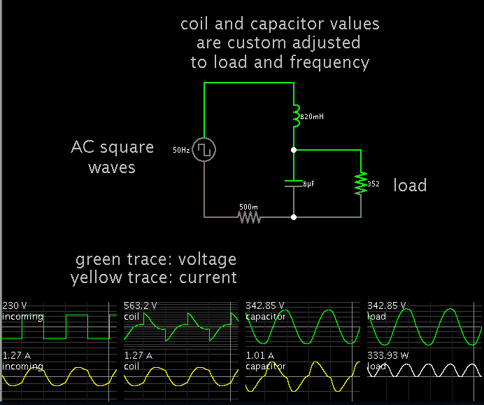
I need some urgent help. For our senior design, we are creating a digital UPS system, meaning that all our control signals and switching signals will be generated by an FPGA. So far we have finished designing the charging circuit and the DC to DC converter. We have also been able to do the comparison of the square wave with the triangle wave, to produce the necesary square wave. All that remains to be done is to pass the signal through a filter, which should then produce a nice sinusoidal wave form, except for the fact that we cant figure out how to determine the values of the inductance and capacitance. The output frequency should be 50HZ and with a power rating of approximately 150W. I would appreciate it if someone could help me understand how exactly I should decide on the value of C and L. Thank you!
I need some urgent help. For our senior design, we are creating a digital UPS system, meaning that all our control signals and switching signals will be generated by an FPGA. So far we have finished designing the charging circuit and the DC to DC converter. We have also been able to do the comparison of the square wave with the triangle wave, to produce the necesary square wave. All that remains to be done is to pass the signal through a filter, which should then produce a nice sinusoidal wave form, except for the fact that we cant figure out how to determine the values of the inductance and capacitance. The output frequency should be 50HZ and with a power rating of approximately 150W. I would appreciate it if someone could help me understand how exactly I should decide on the value of C and L. Thank you!