z9u2k
Member level 1
Hey all,
been doing some reading on single-throw switch debouncing methods, mainly here: Debouncing
I am interested in the RC debouncer presented, but I was wondering if it was possible to lose the inverter.
The inverted debouncer looks like this:
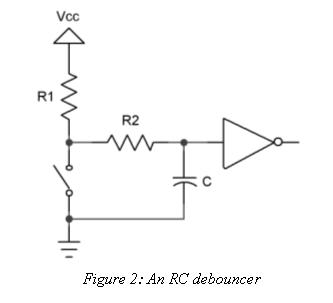
I was thinking that by swapping the switch and R1, and changing component's values, I could get a non-inverting debouncer.
At first, the switch is open, and the capacitor is discharged. The gate sees a logical zero. When the switch closes, the capacitor will be charged through R2 alone. Using a 100nF capacitor and a 390k resistor as R2 I could get 20ms before the capacitor's voltage reaches 2V (assuming a 5V supply), which is the logical high threshold of the uC I'm working with.
When the switch opens again, the capacitor will slowly discharge through both R1 and R2. Using a 10k resistor as R1, I would get about 73ms before hitting the 0.8V logical low threshold of my uC. (if C was fully charged)
Having the logic inverted isn't a problem as having my CMOS input pin leaking about a microamp when held high (would it leak out when held low?) which biases the capacitor to that current times R2.
This would also prevent false triggering when the circuit is first powered up and C slowly charges past the threshold voltage on its way to the idle state, long after the uC has booted (which makes me use a similar circuit on my nRESET pin to prevent the uC from powering up before all peripheral capacitors have charged)
If this works (and please point me where I'm wrong), why is the inverted circuit so popular while I couldn't find references to any non-inverting?
Thanks in advance!
been doing some reading on single-throw switch debouncing methods, mainly here: Debouncing
I am interested in the RC debouncer presented, but I was wondering if it was possible to lose the inverter.
The inverted debouncer looks like this:
I was thinking that by swapping the switch and R1, and changing component's values, I could get a non-inverting debouncer.
At first, the switch is open, and the capacitor is discharged. The gate sees a logical zero. When the switch closes, the capacitor will be charged through R2 alone. Using a 100nF capacitor and a 390k resistor as R2 I could get 20ms before the capacitor's voltage reaches 2V (assuming a 5V supply), which is the logical high threshold of the uC I'm working with.
When the switch opens again, the capacitor will slowly discharge through both R1 and R2. Using a 10k resistor as R1, I would get about 73ms before hitting the 0.8V logical low threshold of my uC. (if C was fully charged)
Having the logic inverted isn't a problem as having my CMOS input pin leaking about a microamp when held high (would it leak out when held low?) which biases the capacitor to that current times R2.
This would also prevent false triggering when the circuit is first powered up and C slowly charges past the threshold voltage on its way to the idle state, long after the uC has booted (which makes me use a similar circuit on my nRESET pin to prevent the uC from powering up before all peripheral capacitors have charged)
If this works (and please point me where I'm wrong), why is the inverted circuit so popular while I couldn't find references to any non-inverting?
Thanks in advance!
")