Continue to Site

Welcome to EDAboard.com

Welcome to our site! EDAboard.com is an international Electronics Discussion Forum focused on EDA software, circuits, schematics, books, theory, papers, asic, pld, 8051, DSP, Network, RF, Analog Design, PCB, Service Manuals... and a whole lot more! To participate you need to register. Registration is free. Click here to register now.

Need to sense 3watt/230v ac motor current.

Status
Not open for further replies.

Ranbeer Singh

Full Member level 5
Joined
Jul 30, 2015
Messages
259
Helped
22
Reputation
44
Reaction score
22
Trophy points
1,298
Location
Faridabad India
Activity points
3,266
Hell experts,

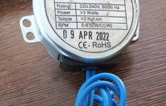
I have a 230vac 3watt motor and want to sense it's current for over current protection. I can not use a current transformer available in market due to very low power consumption and less accuracy. Motor nominal current will be approx 0.012A to 0.02A.

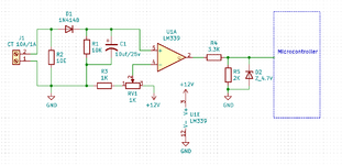
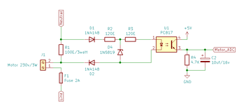
Please suggest me a better circuit.

Thanks in advance
 

Attachments

  • 20220917_152301.jpg
    20220917_152301.jpg
    1.8 MB · Views: 114

Hi,

a suitable solution depends on much more than just "3W motor".

overcurrent protection:
.. means what?
* switch OFF after 10ms of overcurrent, or 5 minutes .. with or wihtout automatic power ON?
* or limiting the current by reducing the voltage?
* What "current" are you after? True RMS, rectified average, peak or just a coarse current information?
* Do you need a true current "measurement"? For displaying it for example..
* how do you adjust threshods (pot, fix, microcontroller...)
* and how do you adjust timing
* is it jsust for protecting the motor? (does the motor need protection at all?) or some other "error monitoring"?

Give bit more informations what you want to achieve.

My first idea: a non isolated current measurement with a shunt.

Klaus
 

Thanks for your reply....

Basically i need to generate a alarm when motor current cross the permissible limit or lower the nominal current.

No need any type of motor current/voltage control circuit. It's just testing the motor is working fine or not.

If i able to use a CT. I use a comparator ic like as lm339 to compare input+ and input- voltage and generate a alarm indication. But due to very low current consumption, i need a little accurate circuit for this like as shunt resistance or any specific ic for this perpose.
 
Last edited:

Hi,

in post#1 you talk about "protection". What gets "protected" and how?
Or is it just an alarm without any protection?

CT and comparator:
It odes not work as you describe. The current is AC.

An example: if the current is 15mA RMS then you have about 20mA peak or 40mA pp.
The current continously changes from 20mA to -20mA and back.
So the compartor output will continously go ON and OFF.
You might use this signal .. but you need to prosess this to drive the alarm.

I don´t know what "alarm" this is, whether you need isolation or not, What power supply you have.. and so on.

Please try to provide all informations at once. Not piece by piece....
A drwaing surly would be very heplful

Klaus
 

Please try to provide all informations at once. Not piece by piece....
A drwaing surly would be very heplful
We use the attached circuit for 10A:1A CT. But for this motor we need a some accurate circuit.
My first idea: a non isolated current measurement with a shunt.
I was looking for the same as you described. Shunt or hall effect based linear current sensing circuit.

No matter, we using lm339 output for protection or alarm perpose.
 

Attachments

  • CT_Circuit1.png
    CT_Circuit1.png
    26.5 KB · Views: 116

Your load calculates as 16 kohms. By installing a low-ohm resistor in series, it creates a few volts drop in proportion to Ampere level. This provides a common means to measure current. It uses miniscule power, generating only a few tens of mW of heat.

In your case a 70 ohm resistor generates in the area of 1 V drop. Adjust the value until it turns on a transistor when it gets high enough.
 

I can not use a current transformer available in market due to very low power consumption
You do know that you can wrap multiple turns of the current-carrying wire through the CT core to increase the sensitivity of a current transformer.
Thus 10 turns would increase the sensitivity by 10 times.
 
  • Like
Reactions: FvM

More generally, a CT can be made with any number of primary and secondary turns. It's just a transformer with the secondary shorted by a shunt. Basic advantage over other current sense solutions is isolation of the measurement circuit.

Your functional descriptions involves two thresholds and can't be implemented with one comparator. You might consider analog measurement by uC ADC instead.
 

for an isolated overcurrent signal, use a resistor to trigger an opto at the peak of 12mA and another at the peak of 20mA ... easy and straight forward and isolated .....
 
You do know that you can wrap multiple turns of the current-carrying wire through the CT core to increase the sensitivity of a current transformer.
Thus 10 turns would increase the sensitivity by 10 times.
Realy i was thinking about this. If i use 10 turns 18awg wire in primery and 10 turns 18awg in secondary. It will be 1:1 CT and easily solves my problem. I also attached schematic for same.
 

Attachments

  • CT_Circuit2.png
    CT_Circuit2.png
    35.4 KB · Views: 113

Hi,

I personally
...would minimize the hardware effort and feed the AC to the ADC (DC shifted for sure) .
So you are most flexible to adjust all you want with software.
Timing, threshold levels ....

Also it is long term stable. No dry out of the electrolytic capacitor.
And cheap...

Klaus
 

I personally
...would minimize the hardware effort and feed the AC to the ADC (DC shifted for sure) .
So you are most flexible to adjust all you want with software.
You are right, we can use direct ac to adc. But need some protection against any type of high voltage spike and short circuit in primery. We can remove capacitor and discharge resistance.

Now my question is... 1:1 CT will work that i descibed (10 turns of primery and 10 turns of secondary in a single CT core)?
 

Hi,

Basis on you given advices, i maid a circuit as attached. It works fine for over current and motor not connected perpose. But today i tried to connect a short circuited motor to our circuit. It burned out resistence R2 and shorted to diode D4 also due to the high voltage/current flow.

My concern is how to protect sensing circuit when motor short circuit.
 

Attachments

  • MTR_Sch.png
    MTR_Sch.png
    11.3 KB · Views: 75

Using a more appropriate 100 mA instead of 2 A fuse would at least improve protection. D4 should be zener, not 1N5819 schottky rectifier?
 

Have an isolated flyback......
Put a sense resistor in the neutral to the motor.
Have the ground of the resistor same as the gnd of the sec of the isolated flyback......
Then you have a sense resistor grounded to your cct gnd...
so now just pick your favourite current sense measurement method.....
...and power it from the sec of the isolated flyback.

communicate with it by radio chip using AM on/off modulation....and microcontroller
..sort this last bit from arduino if you want.
..Or scrub the (~£10+£10) radio chip (rx & tx) and use an opto to communicate to/from it.

Bypass the sense res with diodes in case of overcurrent.

Or just detect o/c and turn off a relay
 

My concern is how to protect sensing circuit when motor short circuit.

A capacitor acts to prevent over-current in case the motor goes short-circuit.
By experimenting with values you may find the sense resistor is unnecessary.

Use caution since it's not isolated from high voltage. Give attention to maximum component ratings.

This capacitive drop method can be a way to derive a low-power supply from house voltage. You may find it's possible to trigger your alarm when the led (or optocoupler) passes current when its threshold voltage is exceeded.

capacitive drop 220nF limits current 230VAC 10k load diode led anti-parallel.png
 

Seems like both Hall and CT tend toward bigger current. Any
reason that you don't want to wind your own for higher gain
than the mass market wants? Or, maybe roll your own Hall
effect sensor with multiple turns, not the usual straight-through
lowest-possible-R construction of the power supply targeted
types?
 

Status
Not open for further replies.

Similar threads

Part and Inventory Search

Welcome to EDABoard.com

Sponsor

Back
Top