Continue to Site

Welcome to EDAboard.com

Welcome to our site! EDAboard.com is an international Electronics Discussion Forum focused on EDA software, circuits, schematics, books, theory, papers, asic, pld, 8051, DSP, Network, RF, Analog Design, PCB, Service Manuals... and a whole lot more! To participate you need to register. Registration is free. Click here to register now.

Need suggestions on Frequency Measurement Circuit

Status
Not open for further replies.

cyber_dev

Junior Member level 1
Joined
Apr 9, 2012
Messages
15
Helped
2
Reputation
4
Reaction score
2
Trophy points
1,283
Activity points
1,408
Hi all,

I need to design a circuit to measure the frequency of sinusodial input signal. The max. input voltage is 50V RMS. The max. frequency of signal is 10 kHz.

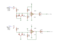
In the schematic shown below there are two circuits for frequency measurement. I tried 2nd circuit with a sine wave over whole frequency range. It works well. But the min. input voltage should be greater than 500mV RMS for proper operation. (I didn't put the cap. in series). It will be better if I measure the frequency even in an amplitude level of 100mV RMS.

Which circuit do you suggest me to use? Is there a need for modification to improve safety and reliable operation? Thanks.
freq_circuit.png
 

None of the circuits will work correctly with TL062 and single supply.
 

Use the second circuit and make R8 ten times as large, this will increase its sensitivity by ten times. All this circuit does is to convert the AC from a sine wave to a square wave. How is the actual measurement to be made.? What sort of accuracy do you require, over what frequency range?
Frank
 

Use the second circuit and make R8 ten times as large, this will increase its sensitivity by ten times.
Would be O.K. with a different clamping circuit.
 

None of the circuits will work correctly with TL062 and single supply.

I forgot to say that I use a single supply rail to rail opamp (TS9222).

@chuckey
I have already tried it (with 10M resistor). But I couldn't get a good result.
%1 accuracy over whole range (0-10 kHz) is sufficient. I will use capture mode of a timer to measure frequency of square wave.

@FvM
Could you explain a little more? What do you suggest for clamping circuit?

Thanks for all the replies.
 

If you do not get any gain increase with a 10Mohm resistor, the opamp is not working correctly. The input signal will be limited to +- .8V, but the output should be able to go from 0 -> Vcc.
frank

Yeah, you are right. But I use schotky diodes so the clamping voltage is 0.3V.

Any further suggestions?
 

The point where the diodes are connected is a virtual earth, which means that the voltage under normal operating conditions are microvolts. Your diodes only protect against gross overloading. As its the inverting input, it sums the currents from the input and output and tries to make them zero. So Vin/R5 = - Vout/R8 . This is why I said make R8 bigger, so you need a bigger Vout to balance the equation. If your amplifier is not doing this, its faulty.
Frank
 

Status
Not open for further replies.

Similar threads

Part and Inventory Search

Welcome to EDABoard.com

Sponsor

Back
Top