Continue to Site

Welcome to EDAboard.com

Welcome to our site! EDAboard.com is an international Electronics Discussion Forum focused on EDA software, circuits, schematics, books, theory, papers, asic, pld, 8051, DSP, Network, RF, Analog Design, PCB, Service Manuals... and a whole lot more! To participate you need to register. Registration is free. Click here to register now.

Need help regarding generating 60hz frequency using 50hz mains

Status
Not open for further replies.
Sorry Venkatesh. I didn't get you.


Actually I modified the Clock freq to 11.095 Mhz.

Code:
#include <REG52.H>
#include <math.h>	
 
void pwm_setup(unsigned char);
void io_init();
 
sbit PWMPIN1=P2^0;
sbit PWMPIN2=P2^1;
 
#define HALF_SINE_TABLE_SIZE 128
#define MAX_SINE_VALUE         0xFF
#define TIMER_CLK_FREQ       11095000
 
unsigned int  Timer_period;
 
unsigned short sine_table[];
	int i,j,b;
	unsigned int table = 64;
	unsigned int clk   = 11095000;
	unsigned int freq  = 60;
	//unsigned int ISR_freq = freq * table * 2;
	unsigned int ISR_freq = 7680;
	//unsigned int timer_period = clk / ISR_freq;
	unsigned int timer_per = 130;
	unsigned int a = 0;
	
 
void main()
{
    io_init();
    pwm_setup(60);
	  
	  for(i= 0; i < (table / 8); i++)
	{
	for(j = 0; j < 8; j++)
		{
	sine_table[b]=65535 - (unsigned int)(timer_per * sin(3.14 * a++/ table) ) ;
			b++;
		}
	b++;
	}

	
	a = 0;
	for(i= 0; i < table / 8; i++)
	{
	for(j= 0; j<8; j++)
	{
	sine_table[b]=65535 - (unsigned int)(timer_per - (timer_per * sin(3.14 * a++/ table) ) ) ;
	b++;
	}
  b++;	
	}
	
    while(1)
		{
			

		}
}
         
void io_init(){
    PWMPIN1 = 0;
    PWMPIN2 = 0;
}         
 
void load_timer(unsigned int Time) {
TH0     = (Time & 0xFF00) >> 8;
TL0     = (Time & 0xFF);
}    
         
void pwm_setup(unsigned char freq){
 
    unsigned int ISR_freq1;
 
    ISR_freq1     = 2 * HALF_SINE_TABLE_SIZE * freq;
 
    //Timer_period = TIMER_CLK_FREQ / ISR_freq;*/
 
    load_timer(timer_per);
 
    TMOD    = 0;
    EA      = 1;
    ET0     = 1;
    TR0     = 1;
}


void timer0() interrupt 1 {
    static int sample = 0;
    static char sign_flag = 0, PWM_out_high = 0 ;
    unsigned int Time_to_load;
    TF0 = 0;
 
    if( ++sample >= HALF_SINE_TABLE_SIZE ) {
        sample = 0;
        sign_flag = !sign_flag;
    }
 ++sample;
    if(PWM_out_high)
    Time_to_load = timer_per - ( sine_table[sample] * timer_per / MAX_SINE_VALUE );
    else
    Time_to_load = ( sine_table[sample] * timer_per / MAX_SINE_VALUE );
    
    load_timer(Time_to_load);        
    
    if(sign_flag)
    {
        PWMPIN2 = 0;
    
        if(PWM_out_high)
            PWMPIN1 = 1;
        else
            PWMPIN1 = 0;
    }
    else
    {
        PWMPIN1 = 0;
        
        if(PWM_out_high)
            PWMPIN2 = 1;
        else
            PWMPIN2 = 0;
    }
 
    PWM_out_high = !PWM_out_high;
}


Here is the output waveform when I remove 1000uF electrolytic capacitor. The freq jumps to 55.55hz with one spike .
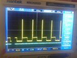
Output.jpg
 
Last edited:

Is it compiles without array size ?


Code C - [expand]
1
unsigned short sine_table[];


The Ram size of the 8051 is less than 128 bytes but your sine table size 128. the program in #41 cant be compiled without changes and it will not work on hardware for 55.55 HZ sine pwm.
 

I think sine wave is generated with 8051. I had seen in some forums but that was using assembly language which I was unable to understand clearly.
 

Its very easy, you need to eliminate the PWM frequency from your sine wave output.

now you are having PWM frequency + Fundamental frequency

You want Fundamental frequency component

So you should design a filter which only allows fundamental component

But not with resistor (resistor will waste the power)
 

Howz that possible? Which values do I need to consider for inductor and capacitor? Please elaborate a bit.
 

First point you have to select a cutoff frequency for your filter.

The cutoff point frequency should be

(10 * fundamental freq) < x < (PWM freq / 10)

If it is closer to left hand side, it will be more smooth but you will have less voltage in terminals

If it is closer to right hand side, You will get ripples in the output.

after that use

cutoff frequency = 1/ (2 * PI * √(LC))

To find L and C values

The L should be enough big to with stand current rating,

The C should be big enough to with stand high voltage and should not be polarity type
 

Thanks Venkatesh.

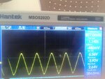
I used third order RC network to get the perfect sine wave and it worked except for the frequency. Previously the freq was 1 hz as you saw. Now it is 1.5 hz when I changed the crystal osc Mhz from 11.095 Mhzto 20 Mhz. That means I should increase the frequency of PWM signals to atleast Khz. (previously it was 55.55hz and now it is 100 hz). I will have to see how I can do it. Either I need to change the timer values or I need to do external triggering.
This is the present output:

Sinewave output.jpg
 

Hi!
I am trying to generate frequency of pwm in khz. At most, I was able to increase it to 100hz by changing Timerper value( to 1, which is last value and crystal osc to 20MHZ). What more I can do to increase PWM freq? Because output is responding to the change in input freq is responding to the change
 

Status
Not open for further replies.

Part and Inventory Search

Welcome to EDABoard.com

Sponsor

Back
Top