ricopt
Member level 5
Any pro out there, pls pls pls help me with my design
I need to wrap up my design tomorrow.Need to settle with this problem
I am currently designing shunt feedback transimpedance with cascode gain stage and source follower.
I am able to get the gain at 525.6 for Rf=1k
but when I simulating Ac analysis with magnitude 1A , my Vout went to large negative value .and my biasing is correct.I can't find any solution to it.I also duno why it happen.Can someone guide me ?

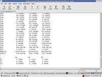
These two are the info regarding the transistors
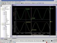
Transimpedance gain

Ac analysis circuit
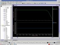
bandwidth
I need to wrap up my design tomorrow.Need to settle with this problem
I am currently designing shunt feedback transimpedance with cascode gain stage and source follower.
I am able to get the gain at 525.6 for Rf=1k
but when I simulating Ac analysis with magnitude 1A , my Vout went to large negative value .and my biasing is correct.I can't find any solution to it.I also duno why it happen.Can someone guide me ?
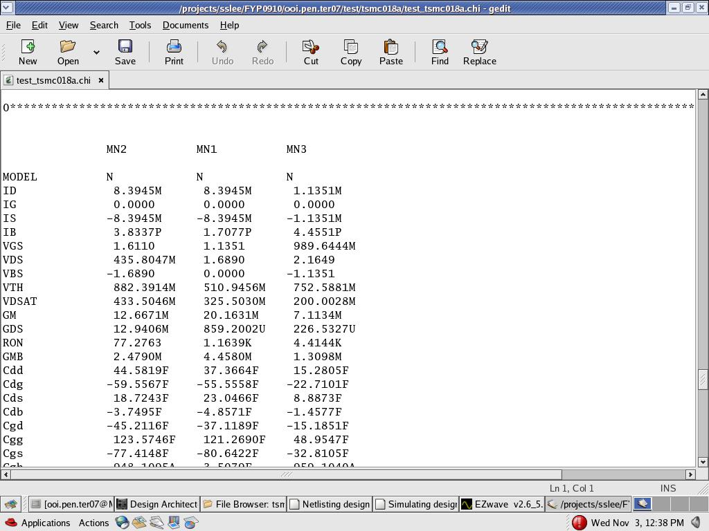
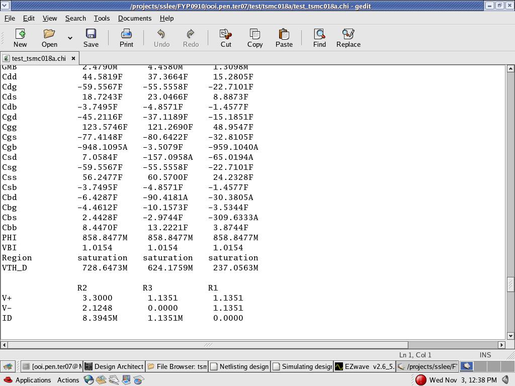
These two are the info regarding the transistors

Transimpedance gain

Ac analysis circuit
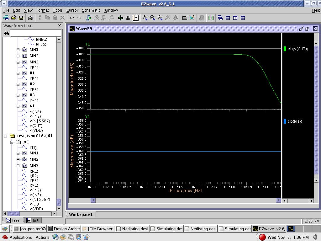
bandwidth