Continue to Site

Welcome to EDAboard.com

Welcome to our site! EDAboard.com is an international Electronics Discussion Forum focused on EDA software, circuits, schematics, books, theory, papers, asic, pld, 8051, DSP, Network, RF, Analog Design, PCB, Service Manuals... and a whole lot more! To participate you need to register. Registration is free. Click here to register now.

[SOLVED] Need for symmetrical dual power supply (-100V & +100 V)

Status
Not open for further replies.

vahid_ff

Newbie level 6
Joined
Oct 20, 2009
Messages
12
Helped
0
Reputation
0
Reaction score
0
Trophy points
1,281
Location
Virginia, USA
Activity points
1,404
Hi,

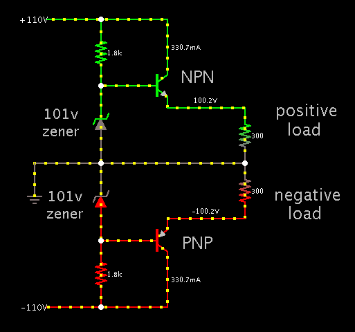
I am going to design a high voltage/high frequency amplifier with apex PA107 and according to the datasheet, it needs both +100V and -100V for supply voltages. off course since the maximum output voltage is not supposed to be higher than 100~120 V (p.p), I think a +70/-70 V power supply is enough.
The output current is in the range of few hundred mA or maybe less.

What would you suggest for the power supply circuit?

* I found tl783 (High voltage regulator) to make positive voltage (<100 V), but unfortunately I couldn't find any negative high voltage regulator that can give us -100V. The only one is Lm337 which can only give us -37V.

Thanks.
 

The differential is limited to 40V (according to the spec sheet). This means you can safely apply -140 V to the LM337, and get -100V out. (I think.)

Or if that is not permitted...

A PNP transistor and zener diode make a simple negative voltage regulator:


The 101 V zener may have to be a string of several lesser values.

The transistors should be rated to withstand the greatest voltage they might be exposed to.
 
I agree with BradtheRad's approach. You don't need high regulation for powering such an amplifier so two emitter-follower regulators, as he shows, should work fine. You can adjust the output voltage by the value of the zener voltage. The emitter output is about 0.65V less than the zener voltage. Just make note of the power dissipation in the zener and the required base current required for your desired output current. Both the zener current and the base current must be supplied by the collector-base resistor.
 
Thank you so much for your helpful response and sorry for my late feedback. Meanwhile, I have some further questions regarding this circuit and I would be thankful if you or other friends help me.

1) Could you please you tell me which Zener diodes and transistors (I mean the part numbers and manufacturers) are the best option for the circuit?

2) Do I need to use a full-wave center-tapped rectifier? (Figure below) or I can use a different (maybe simpler) circuit? Furthermore, do you any suggestion for the winding turn ratio (or output rms voltage) of the transformer?

03444.png

3) Since PA107 also needs and extra voltage supply of ±15V (in addition to ±100V), What do you recommend? Can I use two voltage regulator (7815 & 7915) for this purpose? If the answer is Yes, how should I add them into your suggested circuit?

Thanks :)
 

1) Could you please you tell me which Zener diodes and transistors (I mean the part numbers and manufacturers) are the best option for the circuit?

100V is a standard zener value. You can get by with a 500 mW rating if your PA107 draws a few hundred mA (from one supply polarity).

Transistor specs get complicated when you operate at high volt levels.
Yours need to tolerate 140V C-E. But choose a higher rating, more like 200V. That is the chief spec you will look for in a search.

Yours need to tolerate possibly 40V B-E (140V-100V). This will narrow your choice.

The current might be in bursts of 1 or 2A. So look for ratings of a few amperes C-E.

2) Do I need to use a full-wave center-tapped rectifier? (Figure below) or I can use a different (maybe simpler) circuit? Furthermore, do you any suggestion for the winding turn ratio (or output rms voltage) of the transformer?

You'll need a center tap transformer, 100-0-100. It has to deliver 60W of power from both windings combined (if your project needs 300 mA at each polarity).

You may get by with a 90-0-90, but that is taking a chance.

Do not try to get by with a 70-0-70. It will provide 100V with no load, but that will drop drastically if you try to draw 60W from it.

View attachment 90861

Yes, the above is suitable.

3) Since PA107 also needs and extra voltage supply of ±15V (in addition to ±100V), What do you recommend? Can I use two voltage regulator (7815 & 7915) for this purpose? If the answer is Yes, how should I add them into your suggested circuit?

Thanks :)

You cannot feed 100V to these IC's. The safe maximum is more like 28V. You'll need to construct a separate supply.
 
Status
Not open for further replies.

Similar threads

Part and Inventory Search

Welcome to EDABoard.com

Sponsor

Back
Top