Continue to Site

Welcome to EDAboard.com

Welcome to our site! EDAboard.com is an international Electronics Discussion Forum focused on EDA software, circuits, schematics, books, theory, papers, asic, pld, 8051, DSP, Network, RF, Analog Design, PCB, Service Manuals... and a whole lot more! To participate you need to register. Registration is free. Click here to register now.

Need advice on high current LED strobe circuit

Status
Not open for further replies.

jstamour802

Junior Member level 1
Joined
Jul 22, 2009
Messages
19
Helped
1
Reputation
2
Reaction score
1
Trophy points
1,283
Location
USA
Activity points
1,591
I need some advice on how to connect the feedback from a high-side current source.

Circuit design requirements:
- 48V supply voltage
- LED string length will vary, but can be as long as a ~40V string or more
- LED string must be connected directly to ground to work with an existing system
- Current is controllable from a DAC voltage or similar (0-3.3V)
- Circuit is pulsed, on-time=1usec or more, 0-10% duty cycle depending on current

This one is a bit trickier for me as I need the LED string tied to ground instead. I chose a MAX9643 to output a voltage proportional to the current through a high-side sense resistor, and I plan to use that to regulate the current. The MAX9643 was chosen because it can accept 60V common mode voltages and is high speed - it also looks like the simplest solution until I can work out the rest of the circuit.

The question becomes, how do I tie VOUT from the MAX9643 to an op-amp feedback loop to control the current through the mosfet? I've done some current sinks before and they are relatively simple, but I am not sure how to connect this one up properly.

Attached is a circuit I have in mind but I'm not sure how close I am. Help is appreciated!
 

Attachments

  • Strobe_Circuit_001.png
    Strobe_Circuit_001.png
    44.2 KB · Views: 98

Specs for Current range and min/max PWM?

Up to 50A peak, 1us-1ms. Current output will vary depending on the output pulse-width (thermal limitations and how many capacitors I can fit in the finished package).

Based on a 5VOUT from the MAX9643 (gain of 2.5), a 0.04ohm sense resistor should give the full range up to 50A ( VOUT = ILoad * Rsense * 2.5)
 

Your Mosfet is connected as a source-follower so its output will be maybe 10V less (the gate-source turn-on voltage) than the output of the opamp (less than 24V).
Why are you blinking millions of LEDs (50A!) for such a short duration? Light for less than 30ms appears to be dimmed.
 

Your Mosfet is connected as a source-follower so its output will be maybe 10V less (the gate-source turn-on voltage) than the output of the opamp (less than 24V).
Why are you blinking millions of LEDs (50A!) for such a short duration? Light for less than 30ms appears to be dimmed.

Vision applications, industrial manufacturing, freezing motion for cameras, stroboscopes etc, etc.... this isn't for human vision, so the perceived light output doesn't matter. LEDs used are large arrays, or at least very high current arrays. New high brightness LEDs available can be 10's of watts each, and at short duty cycles can run at 10's of amps without any problems.

I'm not sure I understand your comment about Vgs being 10V less than the opamp. This mosfet's Vgs would be around 4V for 50A drain current according to the datasheet. If it's working as a proper current source, wouldn't Vgs never go above this ~4V mark?
 

Up to 50A peak, 1us-1ms. Current output will vary depending on the output pulse-width (thermal limitations and how many capacitors I can fit in the finished package).

Based on a 5VOUT from the MAX9643 (gain of 2.5), a 0.04ohm sense resistor should give the full range up to 50A ( VOUT = ILoad * Rsense * 2.5)

LED's don't need big Caps and the ESR is very low.
LED's lose efficacy as Ipk/If rated ratio increases >1 .. e.g. Typical 3W LED loses 20% efficacy at Ipk/If=3 using If= rated spec current for efficacy.

Using PWM switch of 48V on a 40V string or less will cause massive Ipk/If ratios due to low ESR.
ESR =~ 1/Pd rated power ( some as much as 50% lower) per LED.

Are these String LEDs or LED Engines?
Pls give LED P/N or exact load specs.

Best solution is a Buck regulated Current source. (make or buy) e.g. Meanwell.

Why string Cathode must be grounded?

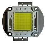
trends for 100W LEDs are towards higher Voltage Arrays of 1W chips. e.g. 60V ,90V etc.etc. with many variations.
100W LED.jpg
 

Mosfets are minimum spec, typical spec and maximum spec. The graphs on a datasheet are for a "typical" one that you cannot buy. You might get ones with minimum spec's.
The datasheet says that a minimum spec Mosfet needs Vgs to be 10V for it to turn on fairly well IF you cool its chip inside it to 25 degrees C (impossible, it will heat up).

You have the Mosfet as a source-follower, not as a switch. For the source pin to be close to +48V its gate must be +58V which is impossible since the opamp has a 24V supply.
Your circuit might produce less than +14V at the LEDs then they will not light.
 

You must use a choke with PWM and clamp diode to regulate current in continuous mode with some margin.
To choose a choke, one must consider the max voltage swing and minimum current swing over integration time.
Vl=L*dI/dt
or use a regulated CC source.
 

I can't use a switching regulator - I have a lot of experience with them and unfortunately they introduce a lot of other issues that I can't have in this design. I've dealt with all the small nuances of drivers like these and theyre are too many trade-offs. I need clean, fast rise-time pulses, so linear is the way to go here.

I need ground-connected LED strings because it needs to fit an existing design, and this is a prerequisite.

And yes the capacitors are necessary. I need 50A pulses from a 4A power supply.

LEDs are typically high brightness ones like these: **broken link removed**

- - - Updated - - -

Mosfets are minimum spec, typical spec and maximum spec. The graphs on a datasheet are for a "typical" one that you cannot buy. You might get ones with minimum spec's.
The datasheet says that a minimum spec Mosfet needs Vgs to be 10V for it to turn on fairly well IF you cool its chip inside it to 25 degrees C (impossible, it will heat up).

You have the Mosfet as a source-follower, not as a switch. For the source pin to be close to +48V its gate must be +58V which is impossible since the opamp has a 24V supply.
Your circuit might produce less than +14V at the LEDs then they will not light.

Is there a "correct way" to configure the mosfet here to work as a current-source switch then? I can use a P-channel as well, or a different mosfet. I'm not locked in here.
 

I don't understand your problem with smooth dI/dt regulator.
You will have significantly more problems with switching 50A in 1 us!!

  • efficacy loss in LEDs,
  • Efficiency loss in I^2 R paths
  • increased EMI radiation dI/dt ( EC/FCC issue far field, logic errors near field)
  • thermal runaway issues if not load balanced

(edit)
So you better explain the real problem before creating new ones.

Let me guess


There are different methods of LED regulation
CV + Rs per string where Rs drop is < 1 LED Vf for tight tolerance supply ( dont use online calculators, N.G.)
CC with constant load power strings in arrays Serial and parallel using high efficiency SMPS
CC with linear regulator ( inefficient unless very LDO CC mode , not typical 2.5V drop)
PWM (CV + Rs) where Vdrop on Rs is smaller than 1 LED Vf ( for efficiency) ( inefficient if Vdrop > 3V)

Define range of LED Load Array of LEDs and supply (CV or CC) desired value and regulator method.
e.g.consider this.

10W LED at 3V has ESR < 1/10W= 0.1 Ohm with 10W/3V=3.3A with approx.Vf
Thus incremental current with RdsOn switch and LED ESR use Ohm's law on difference between string Vf and V+ supply. ESR will be very small so Current pulse Pk/Avg >> 1 means efficient loss due to I² * ESR

If 40V string then 40V/2.9V 13.8 so 13 LEDs in series.
If 14 in series then Vf=14x2.9V =40.6V ( Vf~2.9)
If 15 in series then Vf= 15x2.9V= 43.5
If 16 in series then Vf=16x2.9V 46.4

If using 48V consider regulation error total, lower the better ( 1% much better than 5%)
if 5% then Vmin= 45.6
then choose Vf of string array to be between 1 and 3V ( or < 1 LED drop)

In power LEDs Vf~2.9 @25'C and drops with rising temp)
so 45.6/2.9= 15.7 so choose series string of 15 or ~43.5V

Say you want o make 600W of LEDs from 48V you need >12.5A
Since ESR of 1W LED is ~1/1W @85'C = 1Ω ( my rule of thumb)

An array of 600W LEDs using ~3Vf( could be 20x 30W hybrid LEDs with 6V or 12V option )
An array using 6V (30W) LEDs would be 48V/6=8 in series but 3 strings in parallel is 24 x30W= 720W too much...
An array using 12V (30W) LEDs would be 48V/12= 4 in series (120W) so 5 parallel strings gives 600W (OK)
Thus 4S5P (x30W) is your array and your load is ~ 600W/48V= 12.5A

Unfortunately tolerance on Vf depends on cost and bin number for 30W parts @ 12V
Forward voltage (12 V, @ 1050 mA, 85 °C) 11.6V typical 12.4V maximum (3.3% above 12V or 7% above typ)
If maximum = 2400mA @ 12V @85'C Tj

So if you choose cheaper parts with wide bin tolerance either use adjustable 48V supply upto +3.3%
It appears you may have consider fewer in series 3S7P but voltage is now 36V typ +to ~40V Not good.

Consider adjust 48V to 50V if regulating to 1050mA per 30W LED or 52V if using max of 2400mA with PWM to allow higher bin ESR LEDs ( ie higher Vf, Vthreshold at 10% of If-rated is always the same ~2.7V*4=10.8V) i.e. 10% of 1050mA is 100mA then expect Vf = 10.8V and extrapolate 10.8V + I*ESR to get Vf of device and variance on ESR. Thus 11.6V typ has 0.8V rise with 1050mA ( from datasheet) or ESR=0.8Ω
Recall estimate of 30W 12V LED was 4S8P and 30W from datasheet is 12.7Vtyp*2.4A MAX = 30.5W

Thus 48V supply worst case needs to be 12.7*4= 50.8V so choose 52V for margin. Also suitable for battery backup)
Design CC using ~75mV current shunt to regulate current using MOSFET with <<10% of ESR of entire array.
From data sheet Vf typ @85'C at 2400mA is 12.7V and dv/dT is -8.5mV/°C typ

But to drive 30W lof LEDs Tjc =0.9°C/W @ 85'C=Tj max in 45°C ambient means 40°C rise with 30W = 1.33°C/W - 0.9°C/W = heatsink Rca ~ 0.4 °C/W and ambinet rise from adjacent LEDs cannot occur, if adjacent rise of ambinet was to 85'C you would need an infinite heatsink. So consider a CPU heatsink with fan at 0.1°C/W or a massive passive radiator with convection or force air cooling. So 0.1°C/W is roughly the max you need for cooling. E.g. liquid heat pipes to external passive radiator or distributed LEDs not in one place.

Get the idea yet?
 

Thanks and I appreciate the detailed response.

I have been designing LED illuminators for both continuous and strobe operation for going on 10 years now. I've run the gamut from single 5mm LEDs up to large arrays of hundreds of high power LEDs. I've gone through the exercises that we all do with power LEDs (current hogging, heatsinking, etc..). I've strobed LED arrays in the 50A range with another design we have and it is a proven design (CE certified and in service for almost 10 years now). I have a firm understanding on LED bins, efficacy, behavior in pulsed modes, power consumption, heatsinking etc. We also use an algorithm to limit the pulsed current and duty cycle based on the LEDs forward voltage, dynamic resistance, junction temperature maximums and thermal resistance which has proven very valuable for this type of work. This is all very rock-solid stuff that I've been doing for years.


Lets get down to brass-tacks: I dont need to design the illuminator - assume that the illuminator is perfect and all considerations have been made for the LEDs regarding binning and configuring (we buy reels of LEDs in the thousands which have guaranteed bin ranges).

What I need to design is the current source using the "high side" sensing method, and that is all I'm interested in. It must be linear so it has the best response time. One detail I haven't mentioned is that I will be able to control the output voltage anywhere from 9-48V from a 24VDC input. Assume that voltage converter is perfect and the voltage can be adjusted to meet LED string requirements (plus required overhead).

The design of the high-side current source is the main topic here. I have a low-side (current-sink type) circuit which does this all very well (mentioned above), but new design requirements must move it to a high-side sense. My biggest issue right now is trying to understand how a high-side current source might be configured properly.

Thanks again for your contribution
 

Since you already have a good low-current source but its schematic has not been revealed then why can't you convert it into a high-side current source?
Does your low-side circuit control the current with an N-channel Mosfet? Then use a P-channel for the high-side circuit. Its driving voltage must ne inverted from the N-channel circuit.
 

Status
Not open for further replies.

Similar threads

Part and Inventory Search

Welcome to EDABoard.com

Sponsor

Back
Top