pragash
Advanced Member level 2

i need 7pF to 10pF capacitor at microwave frequency or 2.5GHz. This is for PCB implementation. so any SMT capacitors parts or PCB capacitor implementations are welcomed.
Follow along with the video below to see how to install our site as a web app on your home screen.
Note: This feature may not be available in some browsers.


But if you are really working in this range and have the PCB impedances correctly calculated, multiple small parallel MLCCs of 0201 size (or smaller) should work for you.


Package inductance is mainly defined by the package form factor and can't be reduced at will.
Package inductance is mainly defined by the package form factor and can't be reduced at will.
I expect that PCB trace inductance is even a much bigger problem at the designed impedance level of about 6 ohms.
But if you are really working in this range and have the PCB impedances correctly calculated, multiple small parallel MLCCs of 0201 size (or smaller) should work for you.

Just about any small (0201, 0402) should be more than adequate at 2.5GHz.
Usually, i design RF traces (interconnects) to 50ohm characteristics impedance. for 2.5GHz, trace characteristic impedance have to be 6ohms instead?

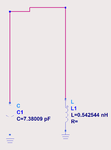
That's what I was thinking - until I looked at the actual data. The issue is the value used here. For such large C with small X, the series inductance becomes relevant even at low GHz. The PDF that you attached also shows the effect - look at SRF of the 7-10pF caps.
.
No, he meant that every length of interconnect will have inductance and matters at these low impedance levels. At the internal nodes inside your circuit/filters, you don't have 50 Ohm impedance levels. The 50 ohm is between the circuit blocks.

No, the impedance generally matters, but it can be analyzed as lumped series inductance and parallel capacitance.The impedance of the interconnect between components (within a filter) doesn't matter if the length of the interconnect is less than 1/20 of lambda.


but i agree every length of the interconnect will have inductance. however, if we increase the interconnect thickness, we can reduce this inductance significantly. shorter and thicker traces are preferred for low inductance.

I doubt that PCB trace plating thickness has a relevant effect on trace inductance. Or maybe you meant width, then I agree. The main rule is: make it short.
Or even better: if you can't avoid interconnect length, make that interconnect part of your design. It adds series inductance, so use a filter structure where that series inductance doesn't damage the response, or possibly improves it.
What filter type do you need to design (filter specs)? What are the PCB space restrictions?
Or even better: if you can't avoid interconnect length, make that interconnect part of your design. It adds series inductance, so use a filter structure where that series inductance doesn't damage the response, or possibly improves it.


I'm designing it.
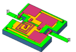
one of the lessons is negative inductance is not bad at all for the spiral inductor. we can still design low loss/high Q negative inductor based on ADS simulation.

You are designing in LTCC technology? 8-O
Then I don't understand your question regarding SMD, because you have so much more options to create "printed" components in LTCC.
I think you need to be careful with that because you are then in a region with strong frequency dependence where small tolerances can shift everything by a large amount.


