Continue to Site

Welcome to EDAboard.com

Welcome to our site! EDAboard.com is an international Electronics Discussion Forum focused on EDA software, circuits, schematics, books, theory, papers, asic, pld, 8051, DSP, Network, RF, Analog Design, PCB, Service Manuals... and a whole lot more! To participate you need to register. Registration is free. Click here to register now.

My WiFi can't meet spectrum mask

Status
Not open for further replies.

rfcn

Member level 2
Member level 2
Joined
Jun 18, 2010
Messages
42
Helped
4
Reputation
8
Reaction score
1
Trophy points
1,288
Location
China
Activity points
1,531
My WiFi with on-chip PA can meet the spectrum mask with OFDM modulation and 10 dBm output power. But it can't meet the spectrum mask with CCK modulation and 10 dBm output power. It failed on the 3rd peak on the double sides of the main spectrum peak.

Can any experts tell me what causes the 3rd spectrum peak when do CCK modulation? How to reduce 3rd peak power?

Why it meets OFDM spectrum mask but can't meet the CCK spectrum mask?

Regards,
rfcn
 

What is your OFDM and CCK bandwidth?
 

Both the bandwidth of OFDM and CCK are 22MHz. They are following the spcification of IEEE 802.11.
 

You can try to decrease the output power, and observe the MASK. If power decrease 3dB, your MASK pass, it seems that the roll-back of PA is not enough. If not, there should be other causes:
1. such as spurs: you can observe in CW mode, and watch spurs, and finnaly dtermine what cause spurs.
2. Source: are your source meet the MASK?

1. The system meets OFDM spectrum mask but doesn't meet the CCK spectrum mask with 10dBm output power. If reduce the output power to 6dBm it can pass the spectrum mask specification of both OFDM and CCK.
2. In CW mode, the spurs are less than 65dBc, so they should have very little impact on the ACPR.
3. The source is good and meet the spectrum mask.

What confused me is that is the CCK spectrum mask specification is more strict comparing with the OFCM spectrum mask specification?
 

Could you pls paste your MASK? Did you do any budget calculation before design?
You can use a probe to detect the RF signal at each stages. If the last stage PA cause the problem, maybe you should replace the PA. Replace with a higher OIP3 PA.
Before doing that, you can paste-and-try to imprve the IM3.

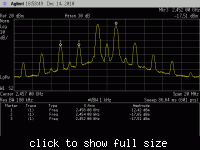
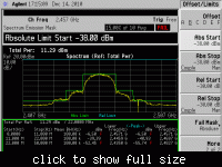
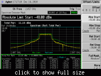
You can find the IMD, CCK mask, and OFDM mask from the attached plot.
From the IMD plot, the IMD5 (marked as 3 in the plot) is too large, which may be the cause of the failure of the CCK specturm mask on the 3rd spectrum peak.

With same output power, OFDM can pass the mask but CCK can't, why?


Yes, you are right, your failure is because IM5, not IM3.
How did you know your output power? Did you measure it on Power Meter?
From the two-tones picture, you can see your output power is 15.4dBm, because single tone is 12.4dBm. maybe because your output power is too high.
What did you do the power detector in your circuits? Use which component?
 

The output power is given by the spectrum analyzer by integrating the power in a specified bandwidth around the center frequency.
The output power in the two-tone test figure is somewhat higher than in the CCK mask figure. Just want to show the impact of the IM5 component.
If IM5 is the cause of the spectrum mask failure, is there any solutions to this problem?
 

AMong the Power Amplifiers class A,B,C and AB which has the higher efficiency and which of them can roduce maximum output power??

---------- Post added at 01:37 ---------- Previous post was at 01:36 ----------

Is there any PA which can produce an efficiency of 125% ??
 

The output power is given by the spectrum analyzer by integrating the power in a specified bandwidth around the center frequency.
The output power in the two-tone test figure is somewhat higher than in the CCK mask figure. Just want to show the impact of the IM5 component.
If IM5 is the cause of the spectrum mask failure, is there any solutions to this problem?

You should use power meter to measure power. When test MASK, the output should be very accurate. What's your output power error? Even in the lower limiter of power, check the MASK can pass or not?

---------- Post added at 03:17 ---------- Previous post was at 03:16 ----------

AMong the Power Amplifiers class A,B,C and AB which has the higher efficiency and which of them can roduce maximum output power??

---------- Post added at 01:37 ---------- Previous post was at 01:36 ----------

Is there any PA which can produce an efficiency of 125% ??
I never heard that efficiency.
 

You should use power meter to measure power. When test MASK, the output should be very accurate. What's your output power error? Even in the lower limiter of power, check the MASK can pass or not?

---------- Post added at 03:17 ---------- Previous post was at 03:16 ----------


I never heard that efficiency.
Ya even i was thinking that an amplifier cannot produce an efficiency more than 75-80% but we were told by our lecturer about this
 

Status
Not open for further replies.

Part and Inventory Search

Welcome to EDABoard.com

Sponsor

Back
Top