shahare.sumedh
Junior Member level 2
- Joined
- Nov 15, 2010
- Messages
- 23
- Helped
- 0
- Reputation
- 0
- Reaction score
- 0
- Trophy points
- 1,281
- Location
- chinchwad, pune
- Activity points
- 1,439
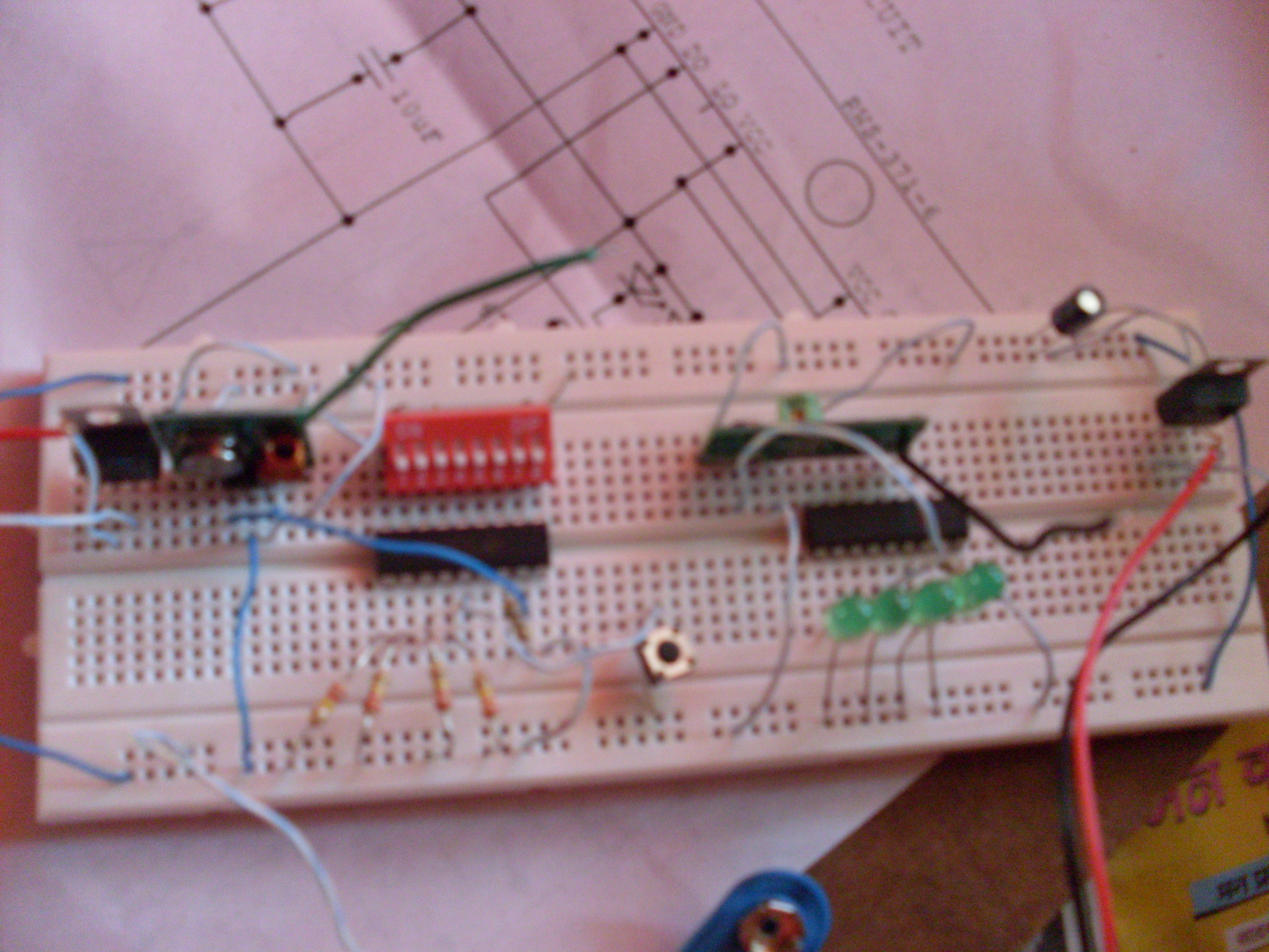
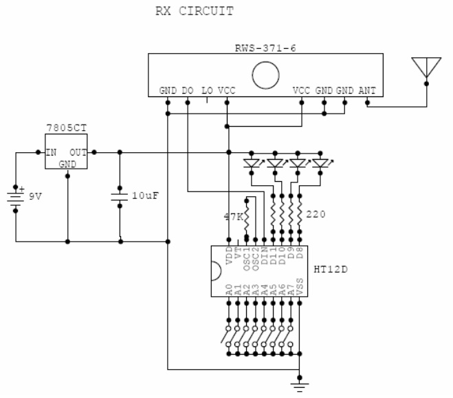
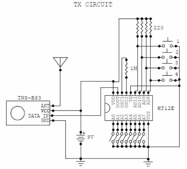
i have connected my rf circuit in the same manner as i have in the diagrams ,, but it is not working......
when i supply 5volts to receiver circuit,, all the LEDs of ht12d glow,,,,,, then when i ground TE pin of ht12e , the LEDs become off, and when i ground one of the data pins of ht12e--- there is no effect on the LEDs ,, please help me........

when i supply 5volts to receiver circuit,, all the LEDs of ht12d glow,,,,,, then when i ground TE pin of ht12e , the LEDs become off, and when i ground one of the data pins of ht12e--- there is no effect on the LEDs ,, please help me........