Continue to Site

Welcome to EDAboard.com

Welcome to our site! EDAboard.com is an international Electronics Discussion Forum focused on EDA software, circuits, schematics, books, theory, papers, asic, pld, 8051, DSP, Network, RF, Analog Design, PCB, Service Manuals... and a whole lot more! To participate you need to register. Registration is free. Click here to register now.

My First receiver:Recommendations-part_1

Status
Not open for further replies.

froten

Member level 3
Joined
Jun 17, 2006
Messages
56
Helped
1
Reputation
2
Reaction score
1
Trophy points
1,288
Activity points
1,798
Hello All,

I'm planing to start building my first project in RF circuits, a SW radio receiver (3-30MHz). I have small experience with RF design so I'm trying to get some help through this forum.

In this post I would like to get some recommendations on the overall design, building blocks, suggested circuits, links and projects.

Since it is the first receiver, it doesn't have to be a high performance, can be Battery or line power operated, and all transistor since IC's are difficult to optain in my city. Any idea is welcome.

Thanks in advance for any help.
 

If is the first RF project should be very simple.
I would recommend a super-regenerative receiver, or a simple superheterodine using NE612, which is easy to get and cheap IC.
On the net you can find a lot of projects like this, with a lot of explanations.
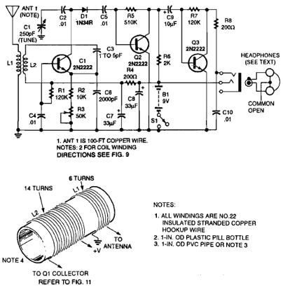
62_1285826848.gif
 
I've got to admit that after working in electronic design for 40 years, the 'super regenerative' design has me confused. Shouldn't there be a connection between Q1 collector, L2, C2, C3 and D1 ?
If there is, it would appear that C7 is part of the tuned circuit. Personally, I wouldn't use 33uF electrolytics as part of any LC tuned circuit at any frequency, let alone at 30MHz !
I also have concerns about using super-regeneration at any low frequency because of the interference it might cause. I would go for a regenerative design instead.

Brian.
 

Thanks vfone for your help.

In this post I'm trying to find out the good and easy approaches to build my project.

Currently I'm thinking about heterodyne receivers, where I will use a tuned circuit at the input of a BJT mixer with tuned collector circuit to IF freq, followed by two tuned stages for IF amplification and then an envilope detector, but any other idea is wellcome.

also I have looked at circuit attached to your replay and It seems to me there is not a collector bias current of Q1? is this intentionally required.
 

If I go back in time, 15 or 20 years ago, and if somebody tell me that Direct Conversion Receiver will be the technology of choice for 80% of the radios on the market, I thought he was joking.
Now, surprisingly (due to their simplicity) super-regenerative receivers are gaining almost the same share market as DCR while ago (RFID, remote keyless, etc).
Of course for top-end quality receivers (especially high frequencies) superheterodine will be hard to be replaced.
Here is a good explanation how super-regen works.
6 Transistor VHF Super Regenerative Receiver
**broken link removed**

Yes, there is a connection point between Q1 collector, L2, C2, C3 and D1.
C7 is not part of the tuned circuit, is part of the DC filter together with C8 and R4.
 

Vfone, I can see C7 is part of the supply filtering but please explain the resonant circuit if C7 is not part of it. There doesn't seem to be a 'cold' end to L2. Shouldn't it at least be bypassed with a capacitor better suited to RF currents, both to improve filtering and to minimize the inductive properties of C7.

Brian.
 

In fact that point it is the "cold" end of L2.
Q1 is a Colpitts oscillator with collector inductor (L2), and also an amplifier using reaction (regeneration bias point find with R3).
A disadvantage of the super-reg receivers is that after each station tuning a maximum amount of reaction should be set (R3 in this case) to get a clear reception.
This was one reason that its inventor (Edwin Armstrong) move step forward and invented Superheterodine.
 
Thanks all for all the help.

I have done some RF circuits in the past and read a lot of text books and web pages put still lacking practical experience, therefore I'm starting with this project at the transistor level.

I have downloaded many old receiver circuits (two links are attached bellow) which I'll try to build a similar receiver (with NPN transistors). I choice these circuit because of low parts count, low current and because I understand the circuit theory of operation. and I'm starting with the mixer circuit.

any advises are welcome.

appreciate ant help.

**broken link removed**

---------- Post added at 20:36 ---------- Previous post was at 18:43 ----------

I would like to know:

1) What is the sensitivity required to build a SW receiver? or what is the expected RF signal value at the input of the mixer? is it in the range of 1uV, 100uV or 1m?

2) What is required gain from the mixer to the detector? 60db,80db or more?

3) What is minimum RF signal value at the detector diode? do we need more 0.7V for the diode to work?
 

Generally the sensitivity of a commercial short-wave broadcast receiver is in 1uV to 5uV range. The total gain of the receiver stages is given by the RF system analysis for sensitivity.
Receiver Sensitivity[dBm] = –174 + 10*LOG(Bandwidth[Hz]) + Noise Figure[dB] + SNR at detector input[dB]
So, for sensitivity 1uV (-107dBm in 50ohms) at antenna input, 9kHz bandwidth, 12dB SNR at detector, noise figure of entire receiver should be approximately 15dB.
Usually 3 stages are enough, between mixer and detector, for this kind of application.
 
I can see C7 is part of the supply filtering but please explain the resonant circuit if C7 is not part of it. There doesn't seem to be a 'cold' end to L2. Shouldn't it at least be bypassed with a capacitor better suited to RF currents, both to improve filtering and to minimize the inductive properties of C7.
You're right; C7 is part of the tank circuit and should be paralleled with a capacitor more suitable for RF. It's done in this circuit which otherwise is almost the same (note that C7 is labeled here as C5):
1416_3.jpg

Above, the connection between the collector of VT1 and the rest of the circuitry is also shown correctly. (Note: R5 should be 150 ohms, not 150k.)
A description (in Russian) for this regenerative (not superregenerative) receiver circuit can be found at cadzone.ru/content/view/561/25/.
 
Last edited:

C7 in the first schematic (33uF) and C5 in the last one 10uF (in parallel to C5 is another decoupling cap C4 10nF), all are fine and they must be decoupling caps. Their connection point in both cases is low impedance and should be "cold" decoupled points, otherwise the circuits will not oscillate.
 

Status
Not open for further replies.

Part and Inventory Search

Welcome to EDABoard.com

Sponsor

Back
Top