Continue to Site

Welcome to EDAboard.com

Welcome to our site! EDAboard.com is an international Electronics Discussion Forum focused on EDA software, circuits, schematics, books, theory, papers, asic, pld, 8051, DSP, Network, RF, Analog Design, PCB, Service Manuals... and a whole lot more! To participate you need to register. Registration is free. Click here to register now.

[moved] Left channel bad - Amplifier in MCS stereo

Status
Not open for further replies.

JJOliver

Newbie level 4
Joined
Dec 29, 2015
Messages
5
Helped
0
Reputation
0
Reaction score
0
Trophy points
1
Activity points
44
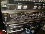
I have a stereo where only the right channel is getting power in the amplifier. Everything else works in this system. Could anyone give me advice on how to identify the electronics I should look at to figure out where the problem is? I placed a picture showing the left channel is not getting power according to the amplifier interface. since this is not getting power, it isnt working on the left side of headphones, speakers and across all components. I am proficient at using a soldering iron if needed, I just do not know what parts inside to look at.
 

Attachments

  • 20151229_123906[1].jpg
    20151229_123906[1].jpg
    3.1 MB · Views: 127

You need to tell us the model number so we can try to trace the schematic diagrams for it.
Also tell us what test equipment you have available, voltmeters etc.

Brian.
 

Mcs 683-2292m
I have a multimeter for testing power... that's all I have
 

This appears to be a system sold by J C Penney in the 1970s so it is probably 40 years old or more and is unlikely to have been exported outside the USA. As far as I know, they did not make their own equipment so the real manufacturer is likely to be an obscure 'far east' company with the branding added later. It is unlikely a service manual exists unless someone has archived one.

Don't give up hope yet though, it is probably more repairable than many more modern units and it probably uses more generic rather than custom made parts so they may be easier to source.

Is it possible to take a photograph of the inside of the unit to give us an idea of the technologies it uses. In particular, a photo of the area around the power supply and the amplifier output stages would be useful, don't bother with the radio or turntable, they are probably OK.

Brian.
 

I used to service Penney's MCS equipment but not in large numbers and it's been like over 20 years ago. First the basics, It looks like all your switches are mechanical and not electronic. While it is playing music, work switches like speaker, tape monitor, etc in and out slowly to see if you hear momentary audio from the dead channel. If so, the switch is bad. Like Brian said, photos will be very useful. Penney's was re-branded from Panasonic, etc. When open, look for brand names like Panasonic, Sharp, etc and maybe other numbers that can be searched.

PS - also when you power on, listen close to the dead speaker and see if you hear a thump, click or hissing sound. That indicates a live output amplifier stage.

Larry G
 

Thank you all for your replies!
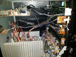
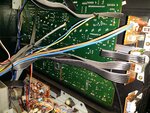
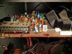
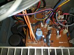
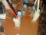
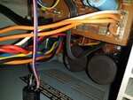
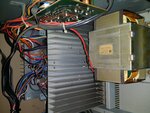
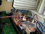
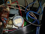
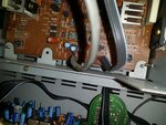
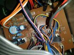
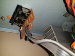
I added photos of the inside.
Yes the .8w (on left channel) led indicates there is power on the front. I heard a very faint sound coming from the headphones on a tape and radio. Almost like a faint tap. It doesn't have a built in turntable.

20151230_091635.jpg20151230_091643.jpg20151230_091652.jpg20151230_091658.jpg20151230_091740.jpg20151230_091755.jpg
 
Last edited:

Picture #4 right center gray capacitor looks swelled? 4.7uf 16v. Is there a power amp IC on those large heatsinks? If so what is the part# on it?
Also see lots of fuses. Could be speaker protection fuse. Check those.

Larry G
 

Posted picture of close up of the grey capacitor I believe you are speaking of. I took more pictures from each side of the system as well. I could not see a part number on the heatsinks.... perhaps if I completely removed it I could find one. Here are more pictures

20151230_103507.jpg20151230_103544.jpg20151230_103956.jpg20151230_104007.jpg20151230_104139.jpg20151230_104151.jpg20151230_104158.jpg20151230_104306.jpg
 

Ok looks like the grey caps are just made that way. Are you just using headphones or do you have speakers? Essentially you have two matched amplifier channels on the board with the heat sinks. Can you tell which side of the board is the good or bad channel? With a meter, compare DC voltages on either the test points or the transistors on first one channel and then the same point on the other channel. Make note of discrepancies. If you hook up speakers and play music at a somewhat loud level, the good channel heatsink should get warmer than the bad channel. If the DC voltages match between the two sides, then not as likely an amplifier problem. Solid state amplifiers are current driven and DC coupled so usually a fault shows up in DC voltages. You may have to gain access to the circuit side of the amp. Be careful not to short pins with your meter or smoke will result !! Of course, keep an eye out for solder or trace cracks.

PS - make DC voltage measurements with no audio playing. The amp will DC balance itself and a problem should be obvious.

Larry G
 
Last edited:

Should I test all transistors? I'll do what you suggested and get back to you. Thanks for all the help!
 

It looks classic 70's Japanese, they had a very characteristic way of building things and it's probably very repairable.

Please follow Retrogear's advice, would also be interested in this test:

1. place you voltmeter black wire on the metal chassis (anywhere near the amplifier). You can usually find a vacant hole to poke the probe in so you have both hands free.
2. Put the voltmeter on a range suitable to measure up to about 50V DC.
3. Find the output transistors, there will be four in total and they will be screwed down to the heat sink. All four may be the same type or there might be two of one kind and two of another. With the red meter probe, touch the center pin of each transistor and report back with the voltage you see.

For safety, wrap some tape around the metal tip of the probe so only the very end is visible, it's easy to short out the transistor pins in such a confined space and that would be disastrous!

With this kind of equipment it is usually quick and easy to find faults when you are experienced. I'm sure Larry would agree that there is a kind of path you follow to isolate the area where the fault lies, the trouble is, if you don't know the layout of the parts, that path could be anywhere on the board!

Brian.
 

Also write down the part#'s on the output transistors. They will be something like 2SD1234. There will be one pair on each heatsink.
If there's a metal clamp over it then don't worry about it yet.

Larry G
 

Status
Not open for further replies.

Similar threads

Part and Inventory Search

Welcome to EDABoard.com

Sponsor

Back
Top