Continue to Site

Welcome to EDAboard.com

Welcome to our site! EDAboard.com is an international Electronics Discussion Forum focused on EDA software, circuits, schematics, books, theory, papers, asic, pld, 8051, DSP, Network, RF, Analog Design, PCB, Service Manuals... and a whole lot more! To participate you need to register. Registration is free. Click here to register now.

[moved] AD9850 DDS Module 2nd channel prob

Status
Not open for further replies.

Naveed_16

Junior Member level 1
Joined
Sep 21, 2014
Messages
16
Helped
0
Reputation
0
Reaction score
0
Trophy points
1
Activity points
122
hiz to all

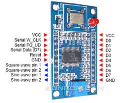
im using AD9850 Module (pic attached)
7011195200_1411499356.jpg


i am confuse about it some parameters:
1: As technical specifications shows, it has two sine wave channels. i got the wave from first channel. how to activate its 2nd sine wave channel
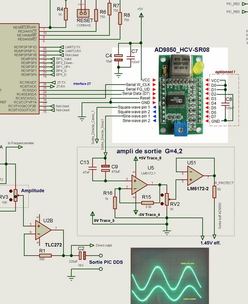
2: Peak-to-peak voltage is too much less, how to amplify it

If anyone has used this module, please help me out
 

You should be able to see the sine wave from the second channel, you don't need to do anything to see the second channel. The second channels output amplitude is lower at higher frequencies so try again at a much lower frequency (say 1Mhz)

You can change the amplitude of the output sine wave by adjusting the blue pot. This pot also adjusts the mark space ratio of the square wave. One of the problems with these modules is that the amplitude of the sine wave reduces with increasing frequency.

A buffer amplifier is recommended for these modules, as connecting a load to the output of these modules can sometimes cause the AD9850 to behave unpredictably. The exact design of the buffer amplifier is dependent on the frequencies of interest.

I sell on eBay software to control these modules programed into a 16F628 PIC, contact me if you are interested.
 

hello,

The level output of this module decrease at high frequency output,
output voltage :
0db until 4Mhz
-3db at 10Mhz
-20db at 30MHz !!

nota: my oscilloscope has 60Mhz bandwidth only..

i used an high speed analog double AOP LM6172 to amplify the signal x 4.2 => 1,45V efficace (instead of 0,37V efficace)
output level 4.2V peak to peak on load=47 ohms and -3db at 12Mhz
you can see my results test **broken link removed**

The 2 analog output (Sin) are with the same frequency, the second output is complementary of the 1rst..
other output are Square instead of sinus.


.
 

this module also have parallel port. i have searched for the example code for parallel interface but havnt found anything.

Do post the code which can be used to interface the module parallel

Regads
 

this module also have parallel port. i have searched for the example code for parallel interface but havnt found anything.

Do post the code which can be used to interface the module parallel

Regads


Hi,

Just curious, have to ask why you want to revert to parallel mode using 10 i/o instead of the more typical serial mode using just 3 ?

If you see the chips data sheet its almost uses the parallel port in a serial fashion as it needs 5 bytes to fill its 40 bit register.

If anyone has done a parallel code version you need to say which micro and language you are using; but then why would anyone want to waste 7 i/os ?
 

in serial senario, the transfer of LO take time to shift to next step. i just want to shift the DDS LO as fast as can.

thats why i want to use the parallel port of the AD9850
 

Status
Not open for further replies.

Part and Inventory Search

Welcome to EDABoard.com

Sponsor

Back
Top