Continue to Site

Welcome to EDAboard.com

Welcome to our site! EDAboard.com is an international Electronics Discussion Forum focused on EDA software, circuits, schematics, books, theory, papers, asic, pld, 8051, DSP, Network, RF, Analog Design, PCB, Service Manuals... and a whole lot more! To participate you need to register. Registration is free. Click here to register now.

[SOLVED] [Moved] 8051 Assembler LCD Programming

Status
Not open for further replies.

Maxeyas

Junior Member level 3
Joined
Apr 4, 2016
Messages
28
Helped
2
Reputation
4
Reaction score
2
Trophy points
3
Activity points
278
Hello edaboard forums. I wasn't sure where to post this and hopefully if this is the wrong section an administrator will move this thread to the right place.

To the point.

I'm trying to initialize and lcd and write data to it (displaying chacters). I'm using alot of connection to desired port and therefore decided to use an electronic chip named 74hc138 which accourding to certian code it will adress the correct device. I've decided to put the lcd on 0x6000. I'm initializing the lcd with the proper commands and send data, Burn the program & yet there is only one bar with black box's. This is the code:

Code:
/*
	« Smart Table Project »
	Script Version: 0.1 Alpha
	Porgram Development: Kiel uVision, Assembly Assets.

	Programmers_    	Maxim 'Maxeyas' Zemlyansky    
						Dor 'Dor7539' Istrick          • General Developers	•
	Moderator_			Afik Gilboa                    • Developers Moderator  •
	
	This script is private and is part of diploma project.
	Nobody may edit/adjust this script without developers premission!

*/
// LCD - Main, Decoder Y3 - (011)16 = 6000H
// Data

mov A, #38h // Function Set
lcall SendCommand
lcall Delay

lcall SendCommand
lcall Delay

lcall SendCommand
lcall Delay

mov A, #06h // Display Control
lcall SendCommand
lcall Delay

mov A, #0Eh // Entry mode set
lcall SendCommand
lcall Delay

mov A, #01h // Clears the display
lcall SendCommand
lcall Delay

mov A, #'M'
lcall SendData
lcall Delay

mov A, #'A'
lcall SendData
lcall Delay

mov A, #'X'
lcall SendData
lcall Delay

SendCommand:
mov DPTR, #6000h
clr P1.2 // Setting 0 in RS (0=commands,1=data)
movx @DPTR, A
setb P1.3 // Setting 1 in EN (disabling the lcd)
clr P1.3 // Setting 0 in EN (enabling the lcd)
ret

SendData:
mov DPTR, #6000h
setb P1.2 // Setting 1 in RS (0=commands,1=data)
movx @DPTR, A
setb P1.3 // Setting 1 in EN (disabling the lcd)
clr P1.3 // Setting 0 in EN (enabling the lcd)
ret

Delay: // 100x100 = 10000us = 10 ms
mov R7, #100
D1:	mov R6, #100
djnz R6,$
djnz R7,D1
ret

end

Please help me getting my lcd work. Thanks, Max.
 

Re: Assembler LCD Programming

Hi,

No schematic?
No information about microcontroller?
No information about display..or at least the controller?
Clock frequency, or cycle time per instruction?

Black boxes usually show wrong initialisation.

Klaus
 

Re: Assembler LCD Programming

Hi,

No schematic?
No information about microcontroller?
No information about display..or at least the controller?
Clock frequency, or cycle time per instruction?

Black boxes usually show wrong initialisation.

Klaus

LCD Model M1632,
1-GND
2-VCC
3-VO
4-RS
5-RW
6-EN
7-DB0
8-DB1
9-DB2
10-DB3
11-DB4
12-DB5
13-DB6
14-DB7
This is the connection i have made and by the way the vo (potentiometer is not working for no reason but the display is at the maximum contrast).
What information on the microcontroller? its a development kit from atmel and the microprocessor is AT89C5131A. Check datasheet for more?
Clock frequency is 24Mhz, isn't this helpful for the delay sequance?
 

Re: Assembler LCD Programming

Hi,

Some issues:
Code:
mov DPTR, #6000h
clr P1.2 // Setting 0 in RS (0=commands,1=data) ...[COLOR="#FF0000"]this seems to be "port access" or "bit bang mode"[/COLOR]
movx @DPTR, A..[COLOR="#FF0000"]this seems to be "memory mapped"access[/COLOR]
how is this made. A schematic could really help....

* do you take care about DATA, RS and EN timing according display datasheet?

* after sending the "X" ... what happens then? Then follows the "SendCommand" routine with the "ret" jumping to unknown address...

Klaus
 

Re: Assembler LCD Programming

Accessing the LCD data bus as external memory requires a data latch, otherwise the data already disappeared when EN is activated. Do you have it?

The asm code is jumping into "nirwana" after writing some characters. It's missing an endless loop or other useful action.
 
Re: Assembler LCD Programming

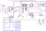
Ok I'll show schematics and explain why and how im using external memory.
The circuit:
Project.png
Ok, please notice the LCD in the schmatic is not connected fully right, the only thing changed in the actual circuit is that VDD is grounded and VSS is going to VCC and Vo does not even effect the LCD, i can literly take it out and the lcd will still work :roll: .

If you can see the 74HC138 using this device to program through external memory, I'm using the ABC to make a code for example if i want the LCD to be in Y3 i make a code 011 and then it gives output 16 bit (0110000000000000 = 6000H).
The RS and EN and RW as in the schematics connected as the actual connection so noting changed there.
The datasheet im using is the HD44780.. the LCD model is M1632.. The crystal is 24mhz.. Its my first time programming LCD.. you ask me alot of questions about this im not sure what to tell you, I'm trying to find answers and instead getting questios s:
 
  • Like
Reactions: ads-ee

    ads-ee

    Points: 2
    Helpful Answer Positive Rating
Re: Assembler LCD Programming

I have also added sjmp $ after the last delay in the code.. now there isn't black boxs but there isn't data either.
 

Re: Assembler LCD Programming

Hi,

either i don´t understand your hardware concept or you totally mixed up memory_mapping and bit_bang modes.

But step by step:
in the actual circuit is that VDD is grounded and VSS is going to VCC
Are you sure?
***

and Vo does not even effect the LCD, i can literly take it out and the lcd will still work
I can´t see why....
***

LCD to be in Y3 i make a code 011 and then it gives output 16 bit (0110000000000000 = 6000H).
Y3 is not connected....so how can it control the LCD access?

***
How can your RESET circuit work without GND?
***
No capacitors at the VCC pins.
***
No capacitors for the ADC VCC as well as signal connections.
****

Conclusion.
* forget the memory mapped concept. It doesn´t work with your hardware (as far as i can see)
* instead control port P2 like an IO port

Klaus
 

Re: Assembler LCD Programming

Hi,

either i don´t understand your hardware concept or you totally mixed up memory_mapping and bit_bang modes.

But step by step:

Are you sure?
***


I can´t see why....
***


Y3 is not connected....so how can it control the LCD access?

***
How can your RESET circuit work without GND?
***
No capacitors at the VCC pins.
***
No capacitors for the ADC VCC as well as signal connections.
****

Conclusion.
* forget the memory mapped concept. It doesn´t work with your hardware (as far as i can see)
* instead control port P2 like an IO port

Klaus

I mean in the actual circuit 1-VSS 2-VDD and in the schematics its 1-VDD and 2-VSS.. its place in the schematics is incorrect.
Yes Vo is not effecting the LCD idk why? I'm connecting a pot named 3296 (W103 = 10k) wiring VSS and VDD to it and the middle to VO and its not changing contrast.
I'll explain how Y3 controlling, well its not, basiaclly its enabled and the rest of the devices connected to Y1,Y2 are not enabled and by using mov DPTR, 6000h im enabling only Y3 and using movx @DPTR, A I'm actually send P0 the content in A its just going through DPTR, thats what my teacher told me to do..
My circuit has RESET and everything works good with it.
VCC pin in the LCD need capacitor? And ADC aswell?

How i'm controling P2 like an IO port? The concept is: Send Commands/Data through P0, enabling them on LCD with pin P1.3 and deciding data or command by P1.2, RW = GND. Thats it!

- - - Updated - - -

Okay i took pictures of my actual circuit. Compare it to the schematics and you'll see what i ment to say. I'm aware my english is bad and thank you for understanding me well!
I have left notes on everything importent there is, if you want more just ask.

Front:
front.jpg
Back:
back.jpg
 

Hi,

Yes Vo is not effecting the LCD idk why? I'm connecting a pot named 3296 (W103 = 10k) wiring VSS and VDD to it and the middle to VO and its not changing contrast.
You see black boxes. That means the LCD controller is not set up yet. So it is very likely that you can not see any change in contrast.

Klaus

- - - Updated - - -

Added:
Do you know that in "memory mapped" mode P0 is a multiplexed bus. It switches from data to low_address and back. every external access. It is controlled by the ALE line.

So when you enable one of your external periferal devices, then they drive to the databus. But with every memory mapped addressing the microcontroller also drives to the databus.
This is an access conflict and may cause short circuit currents.

I´m not very experienced with the 8051, but I don´t think your hardware is made for external memory access.
I know other microcontrollers with similar external memory interface... i don´t think the 8051 is that different.


Klaus
 
Hi,


You see black boxes. That means the LCD controller is not set up yet. So it is very likely that you can not see any change in contrast.

Klaus

- - - Updated - - -

Added:
Do you know that in "memory mapped" mode P0 is a multiplexed bus. It switches from data to low_address and back. every external access. It is controlled by the ALE line.

So when you enable one of your external periferal devices, then they drive to the databus. But with every memory mapped addressing the microcontroller also drives to the databus.
This is an access conflict and may cause short circuit currents.

I´m not very experienced with the 8051, but I don´t think your hardware is made for external memory access.
I know other microcontrollers with similar external memory interface... i don´t think the 8051 is that different.


Klaus

So what do you suggest? Use another port? I have tried to send the data directly to P0 without using 6000H and DPTR.. And its still not showing anything on the LCD.
I'm trying to figure this out for long time, I need one good answer to solve all of this, I have tired alot of different hardware connections and alot of different software codes.
Noting seemed to work out.
 

**broken link removed**
(page 24)
...at beginning:
"wait for 15ms or more after Vdd reaches 4.5V"
....
maybe helping you!
 

"wait for 15ms or more after Vdd reaches 4.5V"
I would expect that the test setup gives sufficient time for LCD power-on-reset. Unfortunately we don't know how the test is performed.
I'm actually send P0 the content in A its just going through DPTR, thats what my teacher told me to do...
Might work, but unrealiable in this setup. Problem is that P0 is open drain output. Regular writing to P0 (MOV P0,A) only controls open drain outputs and can't set high level without pull-up resistors. Writing to external data bus however activates temporarily pull-up drivers and set high level. But it's not guaranteed that the written data is still valid when EN is activated. Leakage currents of connected peripherals can disturb it.

You could provide pull-up resistors for P0 and use regular port output MOV P0,A.
 

**broken link removed**
(page 24)
...at beginning:
"wait for 15ms or more after Vdd reaches 4.5V"
....
maybe helping you!

Added at the top 15ms delay and the lcd doesn't show anything. The sjmp $ command makes the black boxs disapear and removing it will make them reapear.. noting else :bang:

- - - Updated - - -

I would expect that the test setup gives sufficient time for LCD power-on-reset. Unfortunately we don't know how the test is performed.

Might work, but unrealiable in this setup. Problem is that P0 is open drain output. Regular writing to P0 (MOV P0,A) only controls open drain outputs and can't set high level without pull-up resistors. Writing to external data bus however activates temporarily pull-up drivers and set high level. But it's not guaranteed that the written data is still valid when EN is activated. Leakage currents of connected peripherals can disturb it.

You could provide pull-up resistors for P0 and use regular port output MOV P0,A.

I cannot attach pull-up resistors to P0, I don't have enough room on my board for 8 resistors and the storage guy won't let me having those. I need a quick fix noting serious, simple question, is P0 doing the issues? If so i will replace the data bus connection to another port, If you 100% sure about my issue tell me quick options it will help me the most. I can easily say the same as buying arduino and better lcd and making my project on matrix board. Thats a fix too, but my issue here is just lcd not showing up characters, im pretty sure that sjmp $ already initialised him well. Thank you anyway.

- - - Updated - - -

quick update: I have turned the connection from PO to P2 and used mov P2,A and the problem is execly the same not even a single change. Any more ideas how to fix this?
 

I hope you have delay at start before INIT LCD like here:
**broken link removed**
if INIT is OK then LCD go from black 1st line to grayed all lcd!

-Try with oscilloscope if you get signals at PINs
-try with longer delays or try 12MHz quartz
 

I hope you have delay at start before INIT LCD like here:
**broken link removed**
if INIT is OK then LCD go from black 1st line to grayed all lcd!

-Try with oscilloscope if you get signals at PINs
-try with longer delays or try 12MHz quartz

Yes there is dealy. The LCD is not working, there is no simple solution like you said, a delay is there and its not working, already said that million time :/.
At the moment my teacher does the testing with oscilloscope. So i cannot tell you results.
I cannot try 12Mhz quartz, as i said this is all prebuild for me, Look at the pictures at the top i gave everything there is.

Thanks anyway.
 

Programing In Assembly for 8051

Hello edaboard forums.

I have already made a thread about this once and it was really unclear what the problem is. I still didn't solve it after a very long time of trying. I'm going to include every little detail here about my project so you can help me solve it.

Schematics:
Project a.png

Datasheet:

LCD:
**broken link removed**

8051:
http://www.atmel.com/Images/doc4338.pdf

At the moment I'm trying to show a character on the lcd display. Parallel lcd, HD44780.
I'm using 8-bit operation connected directly to 8051 Port 0. Since there is alot of more connections to the same port, im using 74HC138 decoder to decide when each device turned on/off. I gave lcd the 6000h adress.

Now to the problem:
1) When using SJMP $ the LCD will show NOTING.
2) When not using SJMP $ the LCD will show only black bars.
I have been researching A lot. I came to the conclution that the main problem is the delays. I have 24Mhz quarts and i cannot change it.
I thought i might need to use NOP's before clearing EN to send the command/data.
I want to mention that this code below is not showing on LCD noting, but there was a time when i added alot of NOP's between setb EN and clr EN and i saw 2 lines of black bars, Which probably means the first command excuted. Yet with SJMP $ still not a single character showen.

I am 50% sure that the problem is with the delays.
The other problem might be because im flashing with Flip 3.4.7 and the oscillator setup is 8Mhz,16Mhz & 32Mhz. No 24Mhz.

My code (Not working, Noting seen on LCD):
Code:
EN EQU P1.3 // Enable Pin
RS EQU P1.2 // Register Select

lcall Reset
// Insure 8 Bit Mode
mov A, #03h // Function Set
lcall SendCommand
lcall SendCommand
lcall SendCommand

mov A, #38h // Function Set
lcall SendCommand

mov A, #0Eh // Display Control
lcall SendCommand

mov A, #06h // Entry mode set
lcall SendCommand

mov A, #01h // Display Control
lcall SendCommand

mov A, #'M'
lcall SendData

mov A, #'A'
lcall SendData

mov A, #'X'
lcall SendData

sjmp $

SendCommand:
clr RS // Setting 0 in RS (0=commands,1=data)
mov DPTR, #6000h
movx @DPTR,A
setb EN // Setting 1 in EN (pulse)
NOP
NOP
NOP
NOP
clr EN // Setting 0 in EN (send pulse)
lcall Delay
ret

SendData:
setb RS // Setting 1 in RS (0=commands,1=data)
mov DPTR, #6000h
movx @DPTR,A
setb EN // Setting 1 in EN (pulse)
NOP
NOP
NOP
NOP
clr EN // Setting 0 in EN (send pulse)
lcall Delay
ret

Delay: // 100x5 = 5000us = 5 ms
mov R7, #100
D3:	mov R6, #5
djnz R6,$
djnz R7,D3
ret

Reset: // 160x250 = 40000us = 40 ms
mov R7, #160
D4:	mov R6, #250
djnz R6,$
djnz R7,D4
ret

end

* Please before you ask me to change stuff on the board, I cannot change anything, not adding resistor or capacitor or anything. This is the setup and I need to work it out.
* Made some measurements on the resistor 10k connected to VL and its working perfectly setted to 0.5V at the moment. Since the LCD is not showing anything the VL is not effecting it.

Hopefully someone who encountered issue like this before could help me.
Thanks anyhow, Max.
 
Last edited by a moderator:

Re: Programing In Assembly for 8051

Hi,

Please measure the voltage at the LCD pins:
Pin1:
Pin2:

Adjust contrast pot so that on PIN3 you see 0.25V.

******
You need a scope.
Measure signals on LCD pins:
Pin4, pin6, pin10 in one scope screen.
(single shot trigger mode. Press and hold reset, enable trigger, release trigger. )

Klaus

Pin1: 0v
Pin2: 4.5v

Contrust Adjusted to 0.25v.
Noting changed.
Don't have scope, To get one i need to travel very far. Lets say that scope will probably be my last resort to finding the problem.
Anything else?
 

Re: Programing In Assembly for 8051

Hi,

4.5V is not 5V.
Why is it not 5.0V?

With Pin2 = 4.5V you should have -0.25V at Pin3. According datasheet.
*****

Without scope it will be hard.

Additionally the circuit is so confusing. It is mixing several periferal access methods. This makes it very difficult.

With every access to one periferal you need to take care about the other periferals connected to the multiplexed data_address bus.
Therfore I recommend to get rid of the "MOVX @DPTR" instruction.
(See microcontroller datasheet page167 "External Data Memory Write Access" timing diagram. This all happens with your single MOVX instruction. Especially Port0 first switches to output the lower address bits, then it outputs the data bits... all within this single instruction. And your circuit is not made for this!)

***
(I don´t know your ASM instructions, so I have to tell in words. You have to write the true code.)

configure instructions: (port setup)

* Port0 as input (databus)
* Port2 as output (address select part 1)
* output data 0xE0 to port2 (disable all reads)
* port1.0 as output (ADC_WR_n)
* output HIGH on port1.0 (disable ADC_WR_n)
* port1.2 as output (LCD_RS)
* output LOW on port1.2 (init to LOW)
* port1.3 as output (LCD_EN)
* output LOW on port1.3 (disable LCD_EN)
* port3.6 as output (SRAM_RW)
* output HIGH on port3.6 (SRAM_WR = read)
* port3.7 as output (SRAM_DS)
* output HIGH on port3.7 (disable SRAM_DS)

... then we go the next step

Klaus
 

Status
Not open for further replies.

Similar threads

Part and Inventory Search

Welcome to EDABoard.com

Sponsor

Back
Top