Continue to Site

Welcome to EDAboard.com

Welcome to our site! EDAboard.com is an international Electronics Discussion Forum focused on EDA software, circuits, schematics, books, theory, papers, asic, pld, 8051, DSP, Network, RF, Analog Design, PCB, Service Manuals... and a whole lot more! To participate you need to register. Registration is free. Click here to register now.

Mosfet driver signal generator

Status
Not open for further replies.
Re: Power Mosfet driver

Dear Pauloynski, FvM, and the others friends:
My machine operates for periods from 3,5 to 7 seconds of erosion (continuous sparking) and 1 second of pause (head goes up, c recharges, and then goes down). These are standard values, and also can be modificated (for example, increase the pause up to 3 seconds). Now that you have more idea of my project, and now I already saw the site www.innovatia.com, I have some questions: what circuit is suitable to me: The 2nd much-improved circuit of a Noninverting Direct-Coupled High-Side Driver of that site, your last design, or other?
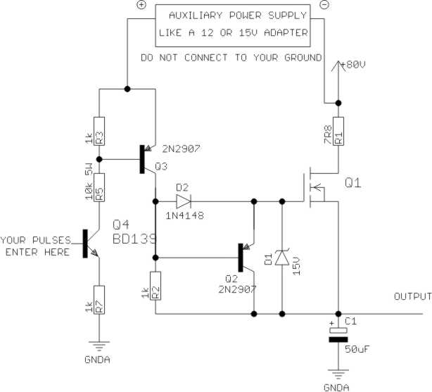
My second stage, is to built an oscillator, could be with an LM555, that will draw the output power mosfet/s, which goes from ton=0,9 mseg and toff=0,1 mseg (f=1KHz) up to ton=toff=5µseg (f=100 KHz); all these values gave me an old Argentinean electronic engineer descendant of Irishmen, who was initiate in the epoch of the valves (vacuum tubes, like triodes) who 30 years ago made the first EDM of Sud America. Can you design me the complete circuit?, because I design one, but my values are strange, and my way of connection with the mosfet are odd too.
This week I’m going to downtown to buy the components.
Thanks.
Luis.
 

Re: Power Mosfet driver

Hi Luis: in my opinion the third circuit shown in www.innovatia.com is fairly superior. The ability to apply up to 15V to the gate will bring the MOSFET to its lowest possible Rdson (not the case with the actual circuit). However, this circuit needs an extra power supply, noted as VGH, which should be something like 20V superimposed on your output voltage. This can be done easily with a small floating voltage obtained from almost any adapter. Please note also that the input transistor (2N3904) may not like to work with such a high resulting voltage (about 100V) at its collector, so it is better changing it (a BD139 could be used). A high-side bootstraped driver will not need to use this additional supply. There are lots of manufacturers (IR, Fairchild, Onsemi, ST, etc) on the market. If you want to use a LM555 to generate the timming pulses, please google for a while and you´ll find lots of stuff like **broken link removed** However, I think it is time to consider using a small mcu (like an Atmega8 or 88) to do this. The advantages are evident: repetitive and reliable pulses and the possibility to add a keyboard and LCD display to the system.
 

Re: Power Mosfet driver

However, if your last opto-coupled circuit will bring me good results, I prefer build it, because I no need another power supply.
When you said: “VGH should be something like 20V superimposed on your output voltage” I didn’t understand if VGH=20v or (20v+83v) and which is the output voltage (how many volts). Sometimes, I have some little problems with grammar comprehension.
Is difficult to me understand the mean of the word bootstrap, so I didn’t understand what is a High-side bootstrapped driver. It’s a kind of feedback perhaps? Also, I don’t know what is a mcu.
Sorry my persistence, but I wanna understand and I have nobody, except you, to ask. In any moment I try to find the way to give you back this favor.
Thanks again.
Luis.
 

Re: Power Mosfet driver

Hi Luis: the original driver is not able to fully drive the MOSFET. If you use it you should expect the MOSFET to heat much more than if you use the correct driver. By superimposing VGH I mean to add this voltage to the charging voltage (i.e. connecting its negative reference (or ground) to the positive side of the charging voltage) and that is why these voltages must be independent (floating) with respect to each other. A mcu is a micro-controller unit or a microprocessor. A bootstrapped circuit obtains this voltage by charging a small capacitor every time you switch your circuit. Google for a while and you´ll find lots of circuits like this https://www.linear.com/pc/downloadDocument.do?navId=H0,C1,C1003,C1142,C1041,P2382,D1706
 

Power Mosfet driver

Altough I previously mentioned a bootstrap gate driver, I'm not sure if a standard IRF highside driver IC will work. In it's usual circuit, it requires the output voltage to go to zero between high pulses, this must not necessary be the case during discharge. Also larger bootstrap capacitors would be needed with 1 ms operation cycles.

I was rather thinking of an application specific bootstrap circuit. I also mentioned the auxilary supply variant, that ha sthe advantage of not depending on a particular output low voltage between pulses.
 

Re: Power Mosfet driver

As I understand, in circuit number 2 of these series (please see attachment) the only reform is change the 2N3904 by a BD139, the gnd connection is the gnd of the 5V that I already have, and between this gnd and the base of the BD139 I switch on the circuit with a 5V level, the VGH is connected to the + terminal of a 20V supply, whose – terminal is connected to the +83Vcc of my Spark power supply, and these are all the connections between the 20 V source and the circuit. It’s ok?
I understand there are logic level type mosfets droved directly from VCC, and also there are Buck converters, but I must decide one of these options, with your help, and thus define the final circuit with all the component values.
Sorry if sometimes I don’t understand anything.
Thanks again.
Luis.
 

Re: Power Mosfet driver

If I didn´t make any mistake your driver should look like this. You can use 2 MOSFETS in parallel if you want (just connect the source and the drain in parallel and add a 10Ω resistor to each gate).

Added after 3 minutes:

You can remove (short circuit) R5 if you want but in this case you´ll have to place a small heat-sink on the BD139.
 

Re: Power Mosfet driver

Thanks friend. As soon as possible, I’m gonna build it.
Next days I hope I’ll be writing in this forum about my success, and bother you about another electronics questions.
Best regards.
Luis.
 

Power Mosfet driver

The auxilarx supply circuit has the basic advantage of low voltage drop, thus the MOSFET power dissipation is reduced and the capacitor can be charged up to the supply voltage.

But it's not fully O.K. as shown. A current limiting for Q3 collector current either by a resistor or by turning Q3 into a current source is needed.

If you change the places of R1 and Q1 (together with the connected gate circuit), Q1 source would be stay at V+ level during on state except for a short transition.
 

Re: Power Mosfet driver

Thank you FvM. I was not affraid about limiting inrush currents. I just copied the circuit as it was with a few modifications. I´m not doing the project, just trying to help. The drain current is already limited by the 7R8 resistor and I thought that limiting the gate current would be of no help. Furthermore, as the original author of the circuit (I suppose) also thinks, Q3 can´t source such a large current that the MOSFET can be damaged. In any case, placing a small resistor in series with the gate is a good suggestion (and Luis, please take it into account because some small problems may not be apparent during development but may cause serious problems during the lifetime of a product).
 

Power Mosfet driver

I rather feared Q3 to be damaged. Also Q3 must have 100V voltage rating, 2N2907 isn't good for.
 

Re: Power Mosfet driver

Dear friends:
I thank you a lot, to you Pauloynski, to you FvM, and also to the others that made comments to realize and build my purpose.
In principle, I’m building your last circuit Pauloynski, but if you FvM have an idea to perform it, please draw me this improvement, thus I can include in my PCB, or explain me this change and tell me the component values, and better, how d’you calculate them.
FvM: If I understand well, you recommend me to remove R1 and replace it between the source and the + capacitor, and connect de Mosfet drain directly to 83VDC, but which are the advantages of this arrangements?
Another doubt: Supposedly, 83vdc/7,8 ohms = 10,64A, but months ago, when I placed a 46A mosfet (in previous circuits) it burns itself before a few minutes of operate. Where was the problem?
Pauloynski: which is the formula by that d’you get the power = 5W of the10K resistor?
Thanks friends, eventually, I would need an extra knowledge, because sometimes I haven’t got certain theory and be unfamiliar with some new technology.
Best regards: Luis.
 

Power Mosfet driver

The suggested change is only meaningful when an auxilary gate driver supply stacked upon V+ is used. Then it reduces the voltage drop at the gate driver transistor.
 

Re: Power Mosfet driver

FvM:
-Which commercial transistor can I choose for Q3? Before this change, the rest of the circuit remains the same or I need to modificate any value?
-To limit the current flowing by Q3 collector what value of resistor (in ohms and watts) must I place? I place it between the emitter and the auxiliary power supply?
-If it’s better, change I the position of R1 placing it between the source of the Mosfet and the + of the capacitor?
I send you my idea (please see drawing). I wait your answer.
Merry Easter for all.
Thanks: Luis.
 

Power Mosfet driver

Hai I am trying to desing a small EDM machine, But i am uable to desing a Pulse generator with variable ON time and OFF time, If u have any circuit for for generation of pulse with independently variable ON time and OFF time please send me the circuit, If u have any Idea about pulse generator based on 555 IC with ON time and OFF time setting, please send me the circuit.

Added after 7 minutes:

Can any one help me in desinging a pulse generator for the EDM machine with independent ON time and OFF time setting.If so, Please send me the pulse generator circuit along with the component values.

Thanking you
 

Re: Power Mosfet driver

Dear friend:
Now, I just try to make run my machine such as is it in the better way, to obtain its maximum efficiency. With my last attached circuit (please see my last comment) I have the problem that the transistor burns itself, and up to now, I don’t know how could I work it out (please reed my last questions). I think if I get that this bad performance don’t happen, my next step will be to control the circuit with an LM555 in astable configuration, an easy job to me, but until I don’t solution my problem, I’m gonna keep stuck.
Best regards and sorry my grammar, ever I have a little problem with some syntax structures: Luis.
 

Re: Power Mosfet driver

dear sir
i am srikrish, can u send me the complete circuit of the EDM machine power supply unit (555 Based).
 

hi my mame is roman y live in rosario argentina ywill be a edm which mosfet I need information of voltage an amprs can you help tank you
 

Re: power mosfet driver

Hi,
I am srikrish R from India, If u have the circuit of the PWM type pulse generator circuit for EDM machine please send me the circuits, please send me the circuits to my email : sri_kri@rocketmail.com.

Thanking you in advance

Srikrish R
 

I have built several EDMs from the following plans I posses:-

Build an EDM
EDM-How To Book
A Spark-erosion Machine----Nodel Engineer Magazine
An Workshop EDM------------Model Engineer Workshop magazine
Now I am interested to build a CNC Wire/Sinker-EDM

Any help please?
 

Status
Not open for further replies.

Similar threads

Part and Inventory Search

Welcome to EDABoard.com

Sponsor

Back
Top