usx
Member level 2


https://imgur.com/aW3aDLV
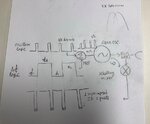
I'm trying to figure out how does this radar system works. Transmit Gunn diode is driven by mixing oscillator logic 3% duty cycle pulse with delta f logic, triggered on the falling edge of oscillator logic by a circuit with two MOSFETs, several resistors and one MOSFET driver to push/pull Gunn diode. If I'm not mistaken, when the two mixed, output to Gunn oscillator should have have slightly different amplitude for pull/push. Transmitted spectrum looks like two frequency pulses close to each other. This part is more or less clear to me. What I don't understand is when I measure output of mixer, there are two IF signals (due to f1 and f2) of slightly different magnitude but they are superimposed. I don't understand why aren't there two separate signals. Are f1 and f2 triggered at the same time?
I need to figure out how this is set up and duplicate modulation scheme on BGT24LTR11 mmic so I don't really want to learn nuances of Gunn and Schottky diodes, I just need to understand how it's done.
I have several radar textbooks by Skolnik, etc but I couldn't find examples of similar modulation schemes with two IF signals sitting on top of each other.
Many thanks
Last edited by a moderator:


