Vermes
Advanced Member level 4
Proper charging process includes two phases: CC – Constant Current, in which the cell is loaded by a specific, constant current. Then, when the voltage reaches the final value of about 4,2V, the second phase begins – CV – Constant Voltage, in which the accumulator is charged by a current voltage 4,2V until the charging current decay.
Sample of MAX1811 system from Maxim:
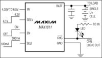
Power range 4,35-6,5V. Final voltage – selectable 4,1 or 4,2V with an accuracy of 0,5%. two charging currents to choose from: 100/500mA (peak currents, in fact, they are typically 455/85mA). The system can “animate” deeply discharged cells – if the battery voltage is lower than 2,5V, the charger goes into preload mode with current about 40mA. When the voltage rises above the limit of 2,5V, normal charging process begins. Thermal protection is also interesting. When the temperature of the structure rises dangerously, current is automatically reduced – when the temperature drops – it is raised. Signalling LED illuminates when the battery voltage is lower than the final voltage – it means that constant current phase is indicated. The LED is off in the event of reaching of the final voltage (although constant voltage phase lasts), so after the LED went out, the cell should be kept in the charger for a while, what allows full use of its capacity.
First drafts of the board were moved to the computer, then printed on laser and ironed.
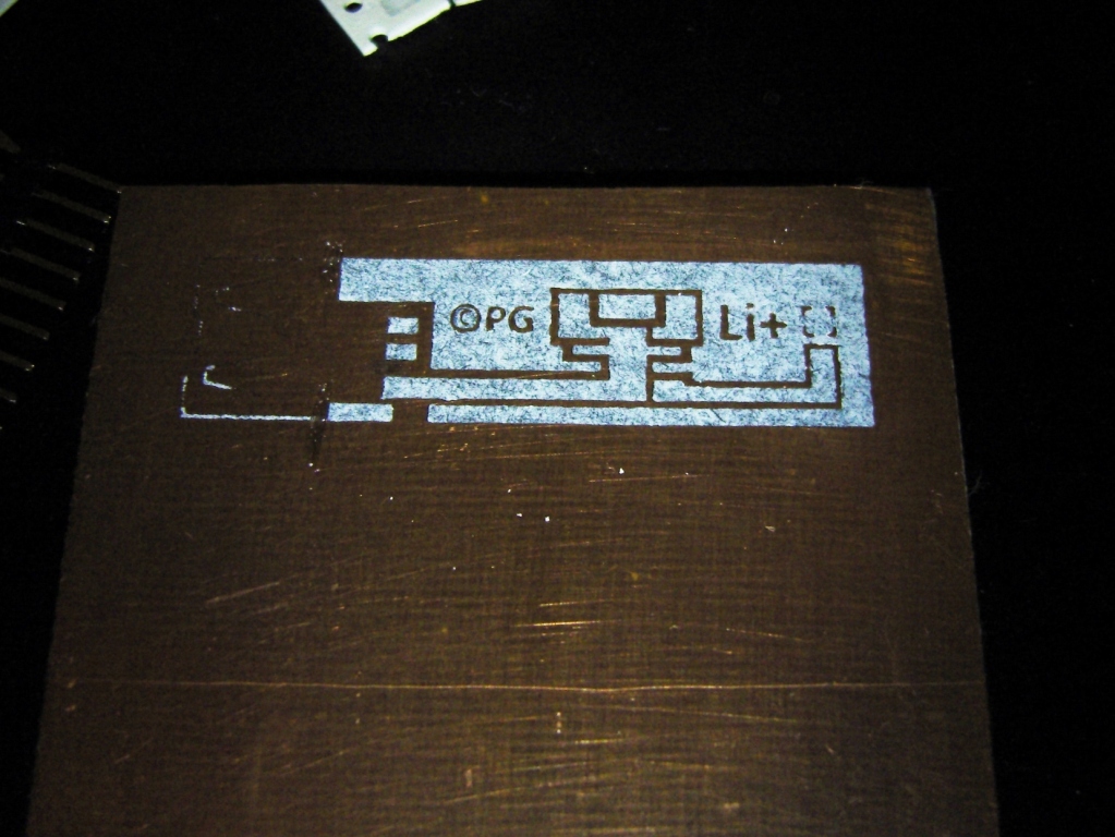
After that, rough cutting, etching and then tin.
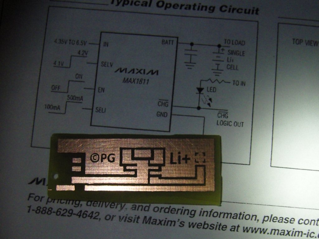

Next, soldering the USB, chip, signalling LED, resistor and two tantalum capacitors (10uF/10V).
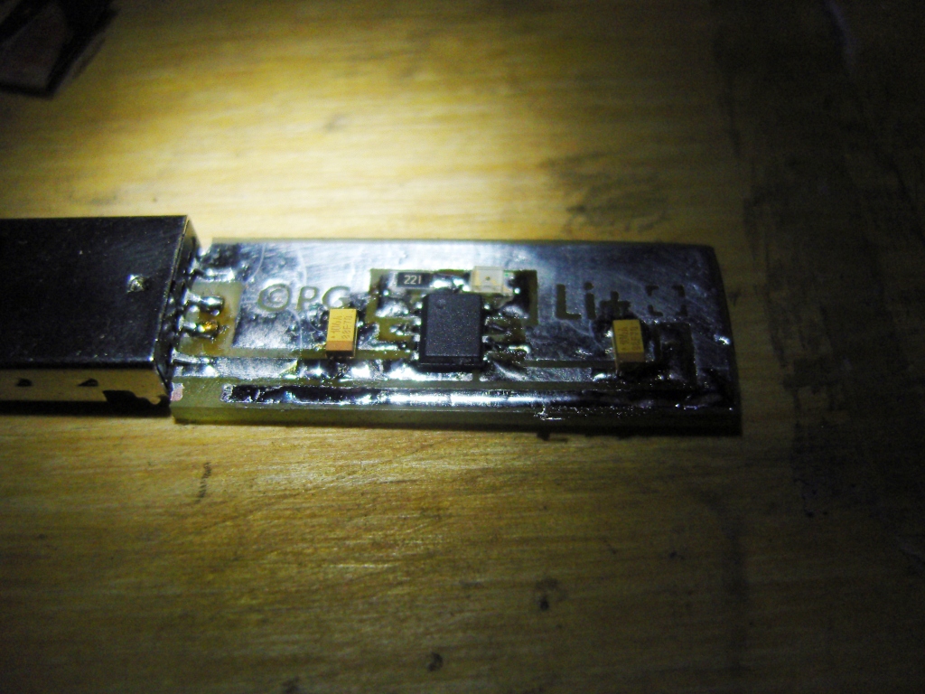
The system sheet recommended that the mass occupied as large area of the plate as possible, because it also serves to heat dissipation from the system. Additionally, a thin copper plate was soldered to the board and wrapped under it.
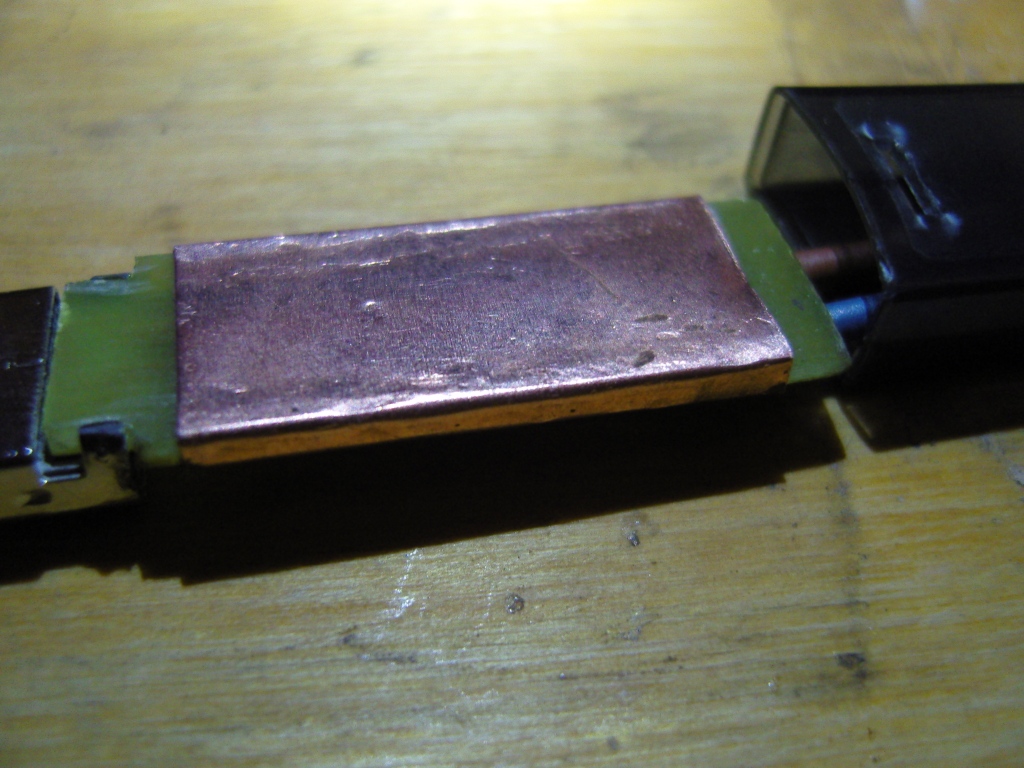
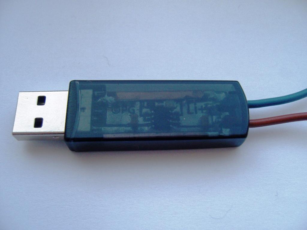
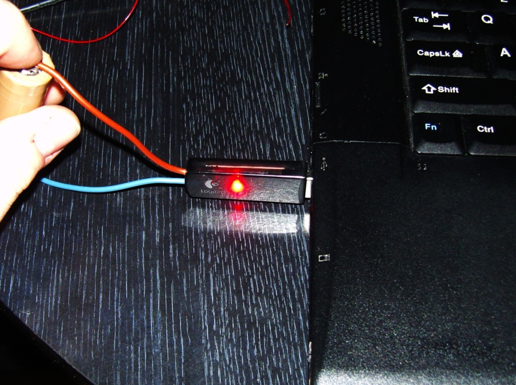
The board was locked in the housing from a wireless mouse receiver. The outputs for the charger are ultimately alligators, which will be connected to the basket with a cell, or on magnets in the case of non-standard batteries.
First tests were okay.
Test
A full test was also made. Two meters: one of them monitors the voltage, the second one the charging current. Data written up to 10 minutes and after going to the phase CV every 5 minutes.
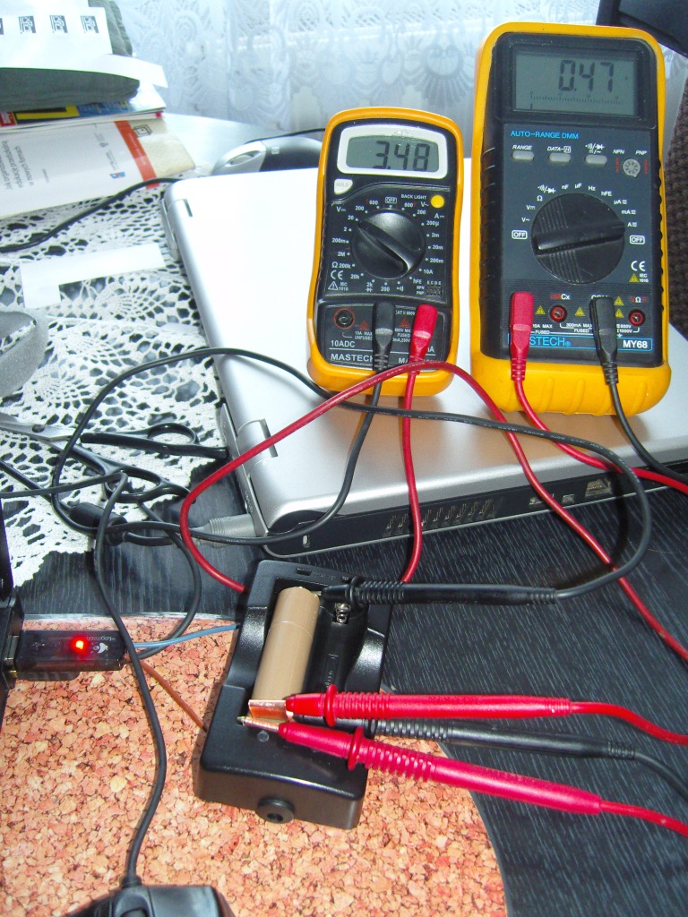
Accumulator is 18650 Panasonic from a laptop battery. It was discharged to 3,2V. In t=0 moment, the battery was inserted to the charger. In the CC phase, the current was still 470mA. After raching 4,14V, LED went out and charging CV started, when the current slowly dropped and the voltage raised up to 4,19V.
Scheme:

Link to original thread – Mini ładowarka USB do ogniw Li-Ion