gres
Full Member level 4
First of all, althought subject is proud, project is very simple.
After I've move to new house I made 4 garden lights. I wanted be able to steering them by remote control or manually.
PROJECT
Simple- normal remote control, typical reference, signal couse start of function. I used RMF12moduls ( very prospective). They run at BASCOM level
I didn't make any schedule because I based on whether station project and documentation for RMF12 modules, I also used parts of code - that responsible for communication with radio module.
REMOTE CONTROL
Button on remote control, starts power of all chipset, so after pressed button, driver starts and send radio signals. Modules RFM12 works with 3.3V, but 3V battery is enough. Atmega 8L need to be prepared to work with lower voltage. Plate shape fit to casing, especially to aerial that is made in print method. Project of aerial I found on internet - works perfect.
(correction) After few days of tests I discovered that 3V battery is not enough for longer time.
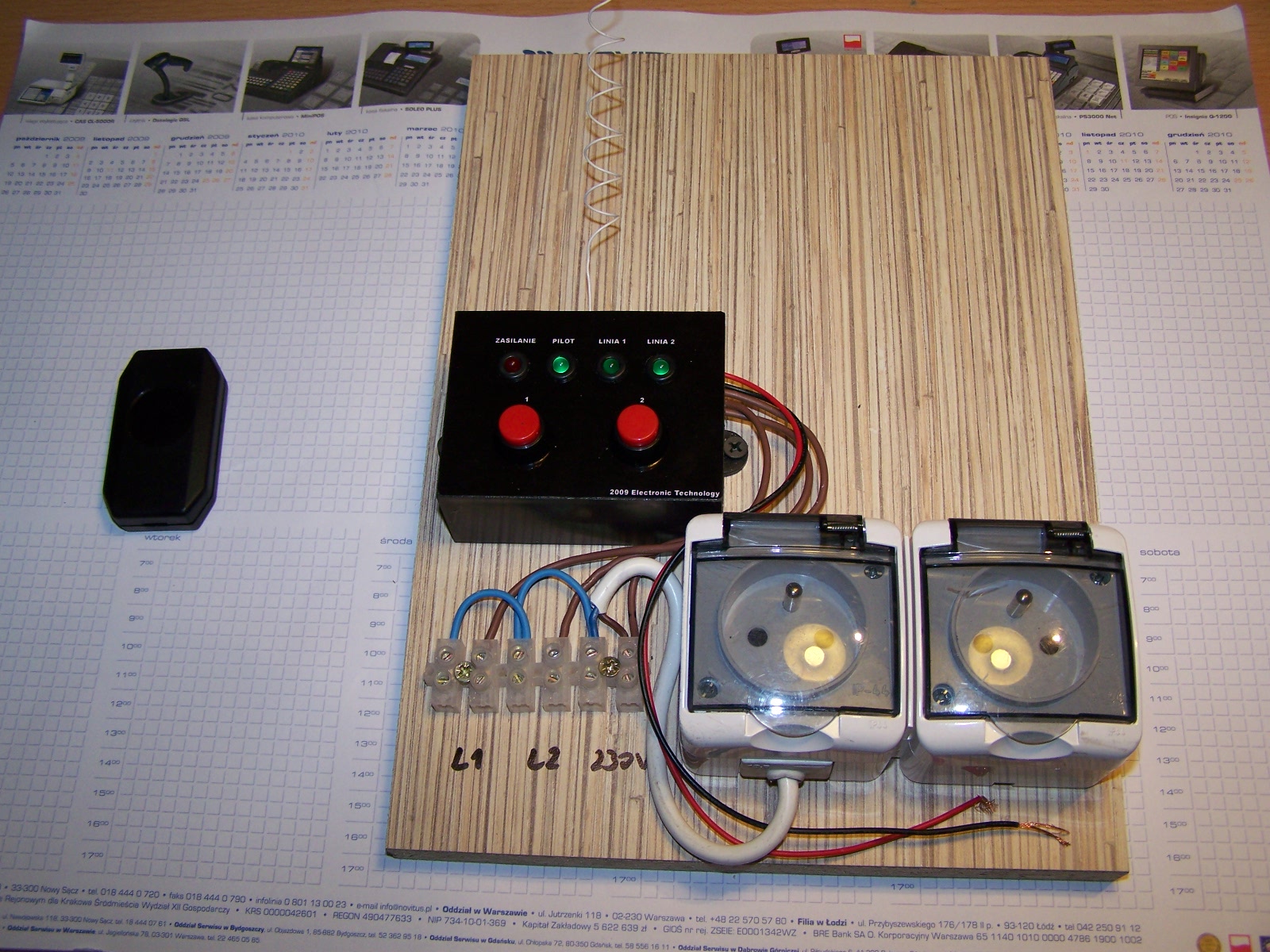
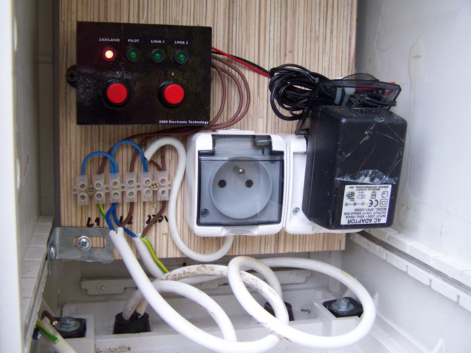
BASE
Very simple - 12V power, stabilizer 5V for Atmega and 3,3 V for RMF12, two buttons as input, diode and two outputs for triacs (of course isolate by optiotracs).
So far power from plug power supply, but I'm going to make few - voltage power supply ( probably I will need 24V for electrovalves).
EXECUTION
Boards for base and remote control I made amateur "iron " method. Design for board I made manually and draw with CorelDraw. Print at all laser printer, then to iron and etch. I was afraid of double-side board, but a grummet for aerial was very useful. Front panel I also designed in Corel and print.
Remote control casing - crib tool from TME. Small clock type battery, glue to casing. Aerial - piece of wire , so far work good.


Text come from:
https://www.elektroda.pl/rtvforum/topic1456118.html?sid=f5951aaa3a108322c7aa571c9231d6cf