Vermes
Advanced Member level 4
It is a design of ignition and gas flow control system for a pulse engine.
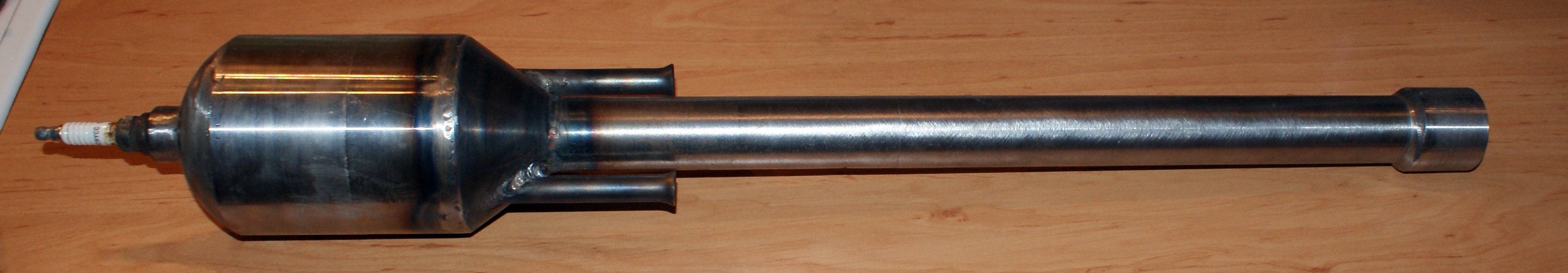
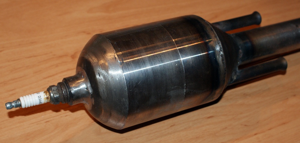
The engine is a container with a diameter of 80mm and a length of 150mm. The ends of the pipe are not flat but arched into a shape which was supposed to look like little balls. This is very important because in the middle there would be strong explosions of air fuel mixture, and flat bottoms, no matter how strongly weld, could not resist. On the one side of the combustion chamber (the contained), there is welded a threaded inside sleeve into which you can screw the spark plug. On the other side, there are welded two pipes with an internal diameter of 8mm and one long pipe with an internal diameter of 30mm and a length of 450mm. Flammable gas from the nozzles will be blown into these two small pipes, and the long pipe will be the outlet of the pulse engine on which you will get the required pulling power.
Description of the engine operation:
The ends of two small pipes on both sides are arched. Using special “hands”, which will be seed in the further pictures, you can put inside them copper pipes ended with a nozzle. This will form a mixer of fuel and air, that uses Bernoulli law – a stream of gas is blown into a tapering tube, in the narrowed part the speed of the gas flowing increases and thus the pressure is reduced. If the pressure is reduced, the air is also sucked in, what creates a kind of pump. A similar phenomenon takes place in gas burners. As a result of gas injection into both such shaped pipes, the fuel-air mixture goes into the chamber.
Next, high voltage pulses are fed to the spark plug causing ignition of the mixture and explosion. The rapidly expanding gas leaks from the central pipe, causing the pulling power. The pipe is also expanded at the end, what, according to the Bernoulli law, causes the pressure increase and thus increase of the pull power. After the explosion as a result of passage of the shock wave through a long pipe, a vacuum is made that sucks up the next portion of the mixture, and again there is an explosion.
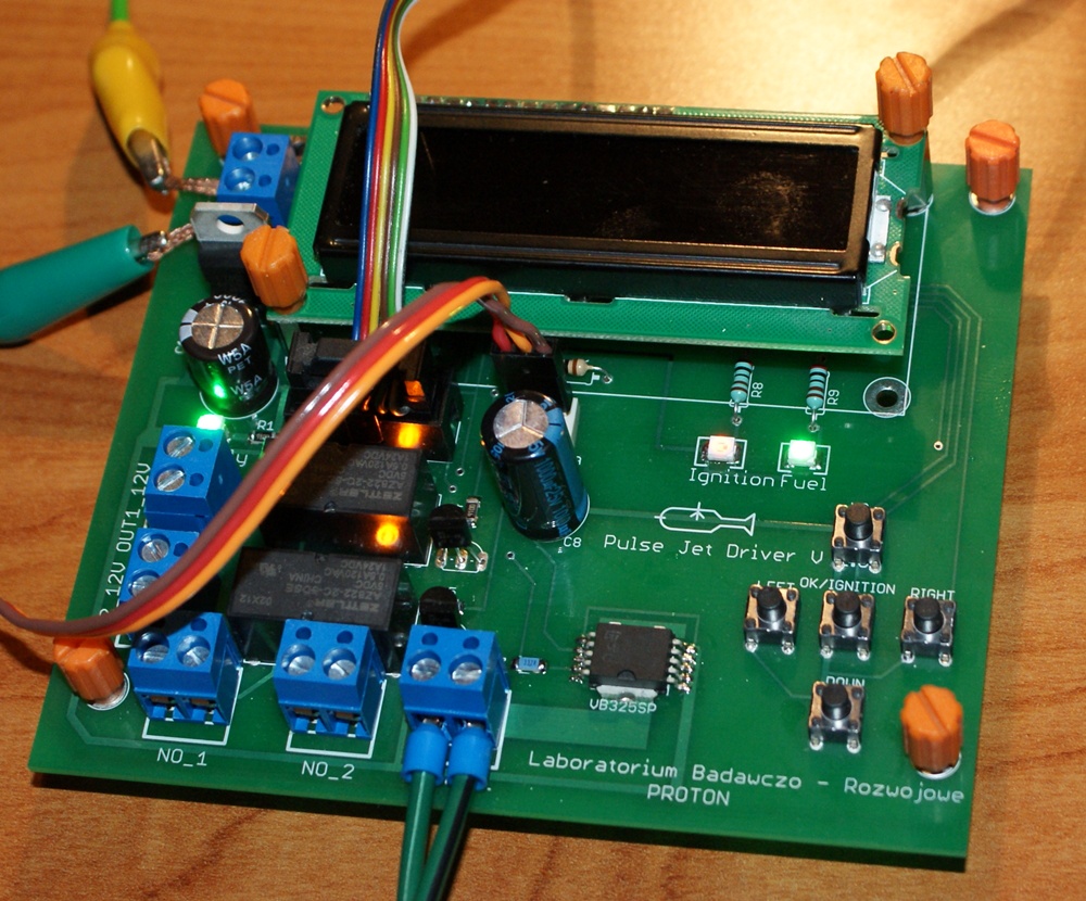
The engine is designed to be controlled from the microprocessor.
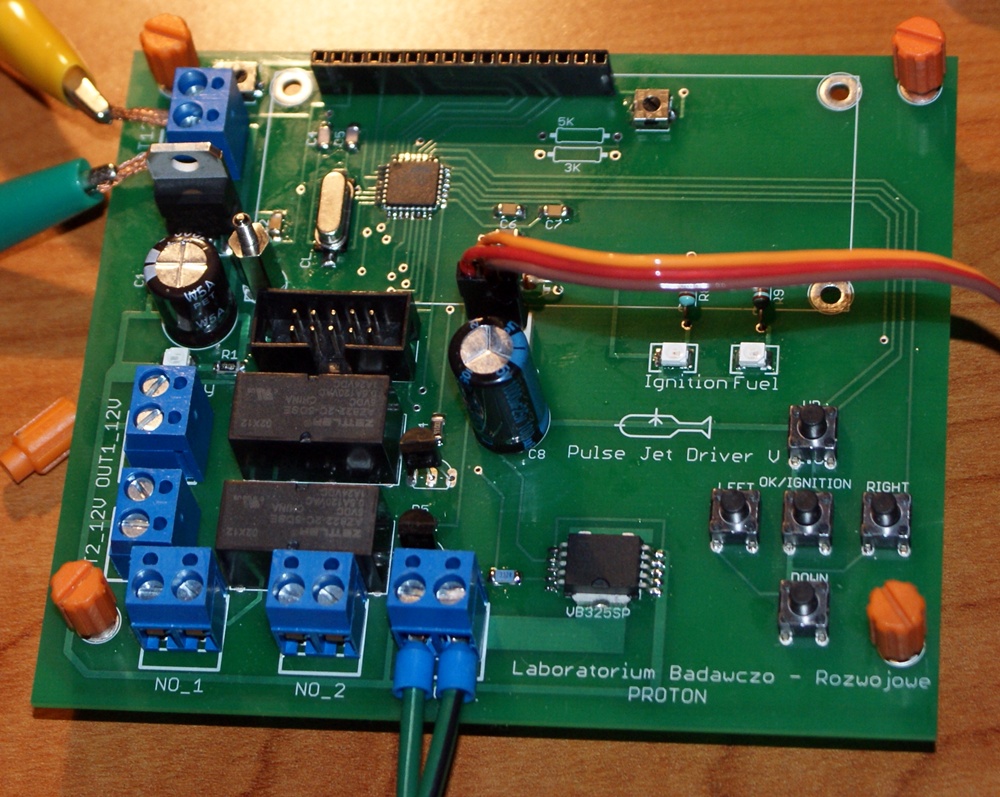
This board implements two basic functions: provides electrical pulses for the ignition coil and controls the amount of gas flowing to the engine.

First of these functions is implemented by means of VB325SP (chip from STMicroelectronics). It is an integrated power circuit with Darlington transistor in the output stage and full logic with TTL inputs. This small chip makes it easier to build the ignition system. Schematic below shows an example application. You just have to connect the ignition coil, power supply and give pulses to the logic input Vin from the microcontroller. In time of these pulses, high voltage will appear on the ignition coil and thus the spark will occur. The chip has also one Enable input, which enables the system off and lock the ignition pulse generation regardless of what appears in the input Vin. The last logic pin is diagnostic output of the chip, the state of which changes when the collector current exceeds 4,5A and when the structure temperature rises too much.
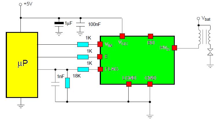
This application uses only the control input Vin. When the power is off, the circuit operates in the following way: when there is a low state in the input Vin, nothing happens. Then, if a high state goes from the microcontroller, the primary winding coil current connected to the power output Hvc starts to rise up to the threshold value constantly set in the system (below 4,5A).
The spark occurs precisely at the moment when Vin state is changing from high to low. If high state is for a long time, a large current up to 4,5A will flow for through the system. There is a frequency generator in the program to provide smooth adjustment of the frequency. When you want it to work properly, you have to make sure that the system generates very short pulses that can accumulate the proper amount of energy in the coil, so that after the state is changed, the spark occurs. In addition, the spark energy can be controlled. By regulating the time of pulse fed to Vin in the range of 4-12ms, you can control the spark energy from very weak and short for approximately 1cm and thick and bright. The maximum frequency with which you can generate ignition pulses with this chip is 150Hz.
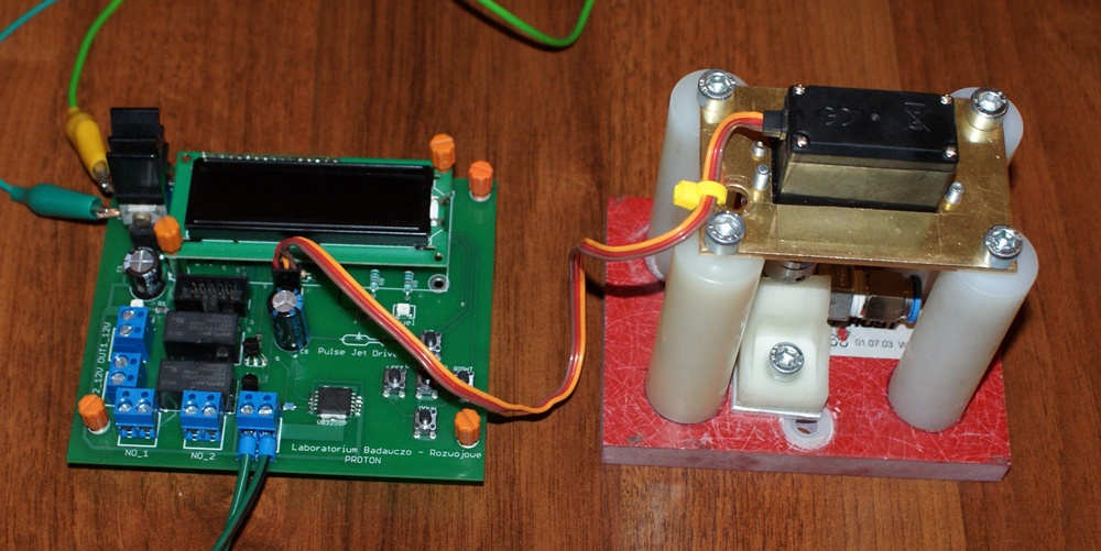

Control of the flowing gas is carried out as a combination of strong modeling servo with a ball gas valve.
Link to original thread (useful attachment) - Mikroprocesorowy układ sterowania silnika pulsacyjnego