Continue to Site

Welcome to EDAboard.com

Welcome to our site! EDAboard.com is an international Electronics Discussion Forum focused on EDA software, circuits, schematics, books, theory, papers, asic, pld, 8051, DSP, Network, RF, Analog Design, PCB, Service Manuals... and a whole lot more! To participate you need to register. Registration is free. Click here to register now.

Metamaterials patches antennas

Status
Not open for further replies.

nina KO

Junior Member level 1
Joined
Jan 3, 2011
Messages
15
Helped
4
Reputation
8
Reaction score
4
Trophy points
1,283
Activity points
1,376
I am currently working on patches antennas metamaterials, I'm stuck on the dimensions of antennas and I do not know how is the design of these antennas in HFSS, I hope someone can help me ! nina:smile:
 

You mean Patch antenna with high impedance surface as ground plane which is a kind of metamaterial or what do you mean here? explain your work or what you are aiming for a bit more!!!
 

Ansoft has a nice document on designing antennas using Left-handed materials. Below is the link:
**broken link removed**
 

Hi everybody ;

In fact, I'm interested in compact metamaterial antennas. I try to show the performances observed using HIS, the CMA and finally with LHM, but I don't advance coz I've a problem with the size of HIS antennas and I don't know how to design LHM antennas. I do not work with CRLH-TL, I have the file about HFSS but it does not help me. Thank You :smile:nina:smile:
 
Hi everybody ;

I have some problems with HFSS simulation of microstrip patch antenna. Please can you show me how te simulate this type of antenna with HFSS. nina :smile:
 
  • Like
Reactions: egf

    egf

    Points: 2
    Helpful Answer Positive Rating
What kind of patch antenna are you designing ?
There are different patch antennas based on the type of coupling used, like aperture-coupled, inset-fed coupled, proximity coupled, co-axial feed coupling and direct coupling etc...
 

Hi sv1437 ;

I'm looking for designing patch antenna fed by microstrip antenna but I've problems with the boundries and excitations. nina :smile:
 

Which simulation software are you using ?
I am familiar with HFSS, if you are also using HFSS, then I can help you out with excitations and boundaries.

Can you attach the image of the patch antenna that you are planning to implement?

-sv
 

Hi sv1437 ;

I'm using HFSS for simulating my projects. I send you my simulation of microstrip antenna may be you can find the fault. I'm wondering if you know how simulate a metamaterial patch antenna ? Thanks. nina:smile:

View attachment patchmicro.rar
 

Hey Nina,

I'm in a similar situation. I'm unsure how to simulate a very large array of my metamaterial without taking tons of computational power. Please let me know if you get this worked out!
 

Hi tranquiltension ;

Actually, I work with metamaterials in application of patch antennas but I don't know how proceed it's particulary problems with dimensions of the antenna and also the boundaries and excitations of my whole antenna structure. First, I must use the AMC structure such as cavities (i.e the EBG structures), then I'll use the LHM but I don't how to do it with HFSS. nina:smile:
 

Hey Nina,

So I've downloaded and looked at your file. It seems like you're more or less on the right track. From what I understand, the radiating patch should be approximately half a wavelength long and the substrate is typically a quarter wavelength thick. Because you have both free space and the material wavelength, however, you must find an "effective wavelength" for the two. From what I've seen, there are analytic solutions to this for long microstrips, but I haven't found any "effective wavelength" or "effective permeability" formulas for a radiating patch. I, personally, would just use the wavelength in the material. You're using Duroid 5880, which has a permittivity of 2.2EpsilonNot - giving an index of refraction of about 1.48.

Say, for example, that you wanted to radiate at 10 GHz. The freespace wavelength at that frequency is 3 cm. The wavelength in the substrate, however, is approximately 2.02 cm. So the patch should be approximately 1 cm x 1 cm. The thickness of your substrate should be approximately 0.5 cm. Also, you should have an infinite ground plane behind the substrate to reflect radiation that goes "backwards". It should be directly behind the substrate. Your solution should be of type Driven Terminal. The terminal should contact two conductors. One conductor should be the reference and should touch the infinite ground plane. The other should contact the patch through the microstrip you've drawn. This is the actual excitation.

I hope that helps a bit.
 

Hi tranquiltension,

Where did you get this info on substrate thickness: " the substrate is typically a quarter wavelength thick". There is no requirement as such.
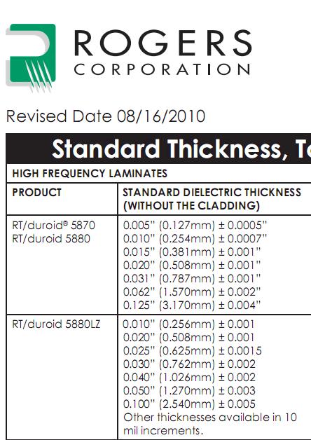
So according to your statement, for 10 GHz, the substrate thickness should be 0.5cm or 5mm for Rogers 5880 substrate. If you look up in the Rogers website, the maximum standard thickness that they have is 3.17 mm for RO5880.

There is no requirement for the substrate thickness to be quarter wavelength because if I am planning to design an antenna at 5 GHz, will it be approximately 1cm?

I think that quarter wavelength requirement is for the radiation boundary.

-sv

---------- Post added at 01:40 ---------- Previous post was at 01:37 ----------

83_1295397638.jpg
 

Hey sv,

From what I understand, there is no "rule" that says the substrate must be of a particular thickness. I've always understood this rule of thumb, however, to be in place such that all the radiation that reflects off the ground plane will interfere constructively instead of destructively with the radiation coming from the patch.

If you were to make the substrate half a wavelength thick, for example, then all reflections from the ground plane would interfere destructively with the forward radiation from the patch and your radiation pattern would be very small.

This is just how I understand it now, though. I don't have a perfect grasp on antennas yet. I'm still learning.

Hope that helps,
TT
 

Hi tanquiltension;

You know, I found an interesting course for you, it contains formulas for the resonant patch antennas. I hope it will serve you. nina:smile:

View attachment course.pdf
 

Hey Nina,

That information is very helpful. I've been looking for this EpsilonEffective formula for a while now. I hope it's helpful for you, also.

Thanks!
- TT
 

Status
Not open for further replies.

Similar threads

Part and Inventory Search

Welcome to EDABoard.com

Sponsor

Back
Top