Continue to Site

Welcome to EDAboard.com

Welcome to our site! EDAboard.com is an international Electronics Discussion Forum focused on EDA software, circuits, schematics, books, theory, papers, asic, pld, 8051, DSP, Network, RF, Analog Design, PCB, Service Manuals... and a whole lot more! To participate you need to register. Registration is free. Click here to register now.

Measuring current between CPC and isolated secondary ground with CT?

Status
Not open for further replies.

cupoftea

Advanced Member level 5
Joined
Jun 13, 2021
Messages
2,611
Helped
54
Reputation
108
Reaction score
115
Trophy points
63
Activity points
13,687
Hi,
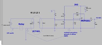
Our contractor has used the ZCT401 CT to measure the current flowing from the CPC earth, to the secondary ground of our circuit (normally, of course, there should be zero current in this connection).
This is a mains distribution box, so the CPC goes straight through it to the load. The secondary ground is the secondary of an isolated SMPS which uses the disty box's mains connection to produce a secondary 24V which gets used by the disty box internal electronics.
In fact, we use a relay to connect the CPC earth and the isolated secondary ground......and this then also switchs in the said CT which then measures any current flow between these two nodes.
The ZCT401 is a "zero phase current transformer", and as such, why is it so suitable for measuring the current in a single 50Hz mains conductor?
The datasheet says "22.5mA". Is this the current that flows in the ZCT401 secondary when its used as a "imbalance torroid" and there's 22.5mA of imbalance?
The attached is how our contractor wants to use it. Do you know what is the turns ratio of the ZCT401 so we can calculate the current in the BAT54's if high fault current flows?
Why hasnt the contractor rectified the ZCT401 output?

ZCT401 datasheet
--- Updated ---

The reay is HF170F

...A 35A, 250VAC relay
 

Attachments

  • CT for CPC connection.jpg
    CT for CPC connection.jpg
    96.4 KB · Views: 111
Last edited:

Some one needs more sleep, it appears the output of the ZCT401 is 17-21mV and there is a figure of 68 ohms specified for something too - let us assume this is the parallel combo of the internal burden resistor ( without which they couldn't specify a voltage - only a current o/p ) and the wdg R.

but there could be a bridge rectifier followed by a resistor inside the CT as they don't specify whether the o/p is AC or DC.

This is a problem until you know for sure how this CT works ...

The fact that it has ( needs ) 4 terminals suggests that there is a 12V or 5V supply needed to amplify the signal from the CT ( it could even be an Hall effect device ) to provide the output, and that the 68 ohms is the Ro of the opamp ...

You just don't know without further info .....
--- Updated ---

Let us assume the simplest scenario ( Occam's ) we want to sense 22.5mA difference current in the CT, if we have a 200:1 turns ratio, we will get a current of

112.5uA in the sec, on a burden of 68 ohms this is 7.65mV or about a third of what is quoted, ideally the burden R would then be ~186 ohms,

and it may be that the parallel combo ( which they measure for test purposes ) is ~68 ohms, i.e. the 200T wdg has an R of ~107 ohms.

Now we would get 22.5mA / 200, * 180 ohms say = 19.98mV AC, which matches the data sheet.

I do not know why the "designer" of your supplied ckt has added the 1k burden R, or why (s)he has chosen only to look at the positive output bits of the CT.

For a fault - say 400A in the CT, the sec current will be 2A until a fuse or other protection ( the RCD relay ) kicks in,

ideally place two inverse parallel 1N4002's across the CT sec to handle this., they won't conduct much at 22mV, but will clamp the fault V to approx 0.8 volt which the op-amp can handle ....
 
Last edited:
Thankyou. This is excellent info you have kindly provided here. -And for your analysis about what might be going on with the schem is very useful.
I am now going to try and work out why the relay is there, and why a CT is used here..ie what fault is going to be detected....that kind of wouldnt be dealt with by other more common methods.

I was hoping that isolated secondary ground and "CPC earth" would be connected all the time anyway....and then this used to "earth" a metal shield round the 20w offline SMPS....to reduce radiated emissions from the offline SMPS.

The fact that it has ( needs ) 4 terminals suggests that there is a 12V or 5V supply needed to amplify the signal from the CT ( it could even be an Hall effect device ) to provide the output, and that the 68 ohms is the Ro of the opamp ...

You just don't know without further info .....
....thanks, youre right, sorry i didnt give the further info.....one pair of terminals is simply for a test resistor and volt source to be connected so the trip level of the CT can be tested...
 
Last edited:

Earth current measurement of LV supply doesn't seem to serve a purpose related to known safety standards. What's the idea behind it? According to post #1, the low voltage circuit is internal only, so the only potential issue handled by the current measurement would be isolation failure of internal components?

Regarding discussion about ZCTxxx data, the specification is incomplete and partly inconsistent. How do you e.g. read the "Output voltage VS turns" diagram in linked catalogue data. It might be possible to qualify the parts yourself by respective measurements, but I would stay away from using it for professional designs without getting complete data from the manufacturer.
 
Status
Not open for further replies.

Similar threads

Part and Inventory Search

Welcome to EDABoard.com

Sponsor

Back
Top