kemalkemal
Member level 1

Hi all
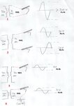
I have a 200V-24V transformer. In order to see waveforms from the secondary side i made some oscilloscope measurements. As you can see from picture i tried 4 setups.
I have found out that 1st one was totally wrong and idotic, because connecting ground clip of oscilloscope probe to one port of secondary winding means that i am shorting that port to earth.
But couldn't understand why there is a difference between 2nd and 3rd setups. The only possible idea came to me is; at 2nd setup, one of the channels act as it is connected to the circuit ground and oscilloscope displayed difference of 2 channels automatically. How this could happen when i didnt attempt to make a subtract operation between channels? Aren't oscilloscope channels independent from each other?
I think the 2nd is the closest to the correct setup. What should be the correct setup?


