Continue to Site

Welcome to EDAboard.com

Welcome to our site! EDAboard.com is an international Electronics Discussion Forum focused on EDA software, circuits, schematics, books, theory, papers, asic, pld, 8051, DSP, Network, RF, Analog Design, PCB, Service Manuals... and a whole lot more! To participate you need to register. Registration is free. Click here to register now.

MC34063A Step-Down Overheating

Status
Not open for further replies.

tlogic

Member level 1
Joined
Oct 5, 2010
Messages
37
Helped
4
Reputation
8
Reaction score
4
Trophy points
1,288
Activity points
1,637
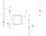
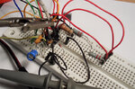
Hello i want to to convert a 12VDC to 1.2VDC (600mA to 700mA). I tried using the LM317 but it overheats very fast so i thought it would be better if i use a switching step-down converter. So i used the MC34063A with the components shown in the attached schematic. About a minute after putting a load of ~100mA the MC34063A starts getting hot and the input current starts increasing as the temperature increases. The component values have been calculated on paper and by this tool **broken link removed** . Also the output voltage is correct (1.2Volt) the only thing i have problem with is that the MC34063 is getting hot and hot by the use.
 

Attachments

  • MC3463A.png
    MC3463A.png
    17.1 KB · Views: 177

Which components are getting hot specifically? If it's the diode, then that's not too surprising, since the output voltage is so low. Make sure you use a good schottky diode. Also what is your operating frequency?

The input current rising is pretty strange. How much does it rise?

A couple other things: make sure you have a decent bypass capacitor on your input voltage. Also, C7 shouldn't be necessary and you should remove it.
 

Only the MC34063A chip is getting hot. The temperature increases in steps and the input current increases like 1mA per second. When i put the load the input current starts about 100mA and after 20seconds of power it is about 120mA and increases.
 

Only the MC34063A chip is getting hot. The temperature increases in steps and the input current increases like 1mA per second. When i put the load the input current starts about 100mA and after 20seconds of power it is about 120mA and increases.
Can you possibly post some oscilloscope waveforms of the voltage at the SWE pin? Preferably just after turn on and then again after the thing heats up. And again, what is the switching frequency?
 

You are sure you don't have to use an external switch to sustain your Iout ?
 

Yes as i read from the datasheet the maximum output current is 1.5A. Also i show a same design at a VFD tube clock called Jenny and he doesn't use an external switch. Here is the schematic of the clock's step down converter

Screen shot 2011-10-01 at 11.03.37 PM.png
 

I tried to take a waveform snapshot at the oscilloscope but the waveform isn't stable to take the snapshot. It changes continuously and it is like a video. Oscilloscope shows that the pulse runs at 150 to 160khz.
 

Is it a digital scope? If so you should be able to just hit stop and capture a couple switching cycles.
 

Yes i can stop it but i don't think that it will be helpful a snapshot like that. I'll take a few and i will post them here
 

I tried with two different Co 166pf (100pf+33pf+33pf in parallel) and 330pf. With 166pf the SE frequency (pwm) is about 120 to 160Khz and with 330pf is about 40 to 50Khz. In both cases the MC chip overheats. At 120khz (166pf) the input current starts from 90mA and at 40khz (330pf) the input current starts from 120mA (the load is same in both cases). I took 2 oscilloscope snapshots with the 166pf connected on Co. The first snapshot is before heating up at 90mA input current and the second is at 120mA after it got hot. I don't think that the snapshots can help btw they look like same.

Note. At these snapshots i also have changed the two resistors R1 and R2 (which configures the output voltage) to 2k2 and 2k2 to give an output of 2.4 Volt. I did it to see if the problem was the low voltage of 1.2Volt or the current to CI but as i see it isn't.

IMAG0202.jpgIMAG0203.jpg
 

Okay, I think that info is pretty helpful. Is your input voltage actually 12V when taking those waveforms? Look at the amplitude of the waveform; it's much less than 12V. It's less because of the current sense resistor, and drop of the switch, which will be 1.0-1.3V (from the datasheet). That will cause a decent amount of dissipation in the chip.

So I'm starting to believe that you're not really doing anything "wrong," and the heating can be explained by the devices normal behavior. To clarify, when you talk about the current, are you referring to average input current or output current? And can you give a rough estimate of the chip temperature. Does it get burning hot, or just warm? Also, can you give an overall estimation of the efficiency of the converter?
 

When i talk about current i talk about the current that draws the MC34063 from the 12VDC Supply Voltage so the input current of the chip. When i took those waveforms the supply voltage was 11.4 measured by the oscilloscope.

I took some temperature measurements. Here you are:

time/temp
00:00/26C
00:27/34C
01:00/42C
02:30/51C
04:00/55C
05:00/58C
06:40/64C
09:00/68C
10:00/70C
11:00/72C
12:00/73C
13:00/76C

The chip is still working but i powered it off not to get burned such as the datasheet gives Operating Ambient Temperature Range 0C to +70C :p
Following a photo of the breadboard what is look like now with the temperature sensor on it. In the photo i also tried to put two 0R2 in series to have 0.4Ohm current resistor for less output current about 300mA to see if there is difference but nothing happens (with same load as before).


MC34063A Testing on breadboard | Flickr - Photo Sharing!
 

Attachments

  • mc.jpg
    mc.jpg
    375.8 KB · Views: 87
  • MC34063A.jpg
    MC34063A.jpg
    375.8 KB · Views: 95
Last edited:

Okay so it looks like you're getting a temperature rise of at least 60 degrees, so over a half watt of dissipation in chip. Definitely abnormal. What's your output voltage and load resistance?

Also what is that small glass diode in the photo? Is that your catch diode for the converter?
 

The output voltage now is 2.4Volt and the load is 10 Ohm resistor which is about 200mA of load. The small glass diode in the photo is a 1n4148 diode which is connected in series with the inductor as shown in the schematic but it is a 1n4148 than 1N5908.
 

that's the point... 1n4148 is not appripriate for this step-down...
neither is the 1n5908 which is a transil voltage spike suppressor...
you must use a 1n5819 as tha diode...
and also you have a lot of step down voltage, the calcs show difficult values for the components in this case.
 

The output voltage now is 2.4Volt and the load is 10 Ohm resistor which is about 200mA of load. The small glass diode in the photo is a 1n4148 diode which is connected in series with the inductor as shown in the schematic but it is a 1n4148 than 1N5908.
Well it's not really in series with the inductor... but yes that diode shouldn't be able to handle the currents you're trying to push through it. It's likely been damaged for a while, and may be the root cause of your problems. I would get a proper schottky diode rated for at least 1A (like the 1n5819) and use that, and propabably switch in a new controller chip since that one is likely broken.
 

Ok. i'm gonna give a try with the MBR1100 that i have for now. It is an 1A SCHOTTKY RECTIFIER

---------- Post added at 17:20 ---------- Previous post was at 16:01 ----------

I tried the MBR1100 but the result is the same... The chip is still getting hot
 

I think the problem is a too high operation frequency (according to the oscilloscope waveforms) and a peak current at the current limit of the device.
 

I have tried with two different capacitors as i said above. 166pf and 330pf. 166pf make it work at 120 to 160khz and the 330pf makes it work at about 40khz. In both cases the chip is heating up
 

The frequency in your waveforms seems much higher however. Isn't it a timebase of 5 us/div?

What are the inductors used in your circuit? Can you acquire the voltage across the current sense resistor to get an idea of the current waveform?
 

Status
Not open for further replies.

Similar threads

Part and Inventory Search

Welcome to EDABoard.com

Sponsor

Back
Top