Continue to Site

Welcome to EDAboard.com

Welcome to our site! EDAboard.com is an international Electronics Discussion Forum focused on EDA software, circuits, schematics, books, theory, papers, asic, pld, 8051, DSP, Network, RF, Analog Design, PCB, Service Manuals... and a whole lot more! To participate you need to register. Registration is free. Click here to register now.

MAX3485 with USB RS-485

Status
Not open for further replies.

ppr92

Newbie
Joined
Mar 4, 2021
Messages
4
Helped
0
Reputation
0
Reaction score
0
Trophy points
1
Activity points
56
Hi there!
This it my first post so thank you in advance for your time!

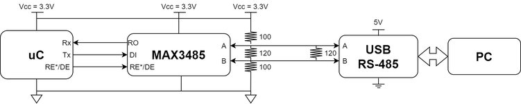
I made a PCB with uC with UART wich I connect to a MAX3485 (3.3V supply). To test it, I tried to comunicate the uC with other devices successfully:
1) ESP32 with external MAX3485 (3.3 levels)
2) ESP32 with external MAX485 (5V levels)

But when I use a USB RS-485 communication doesn't work. I see no response from MAX3485.
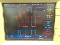
And I see that differential signal A-B is always negative (from 0V to -3V aprox.). My guess is that difference A-B is never >200mV so there will be never a change in RO from MAX3485, but I don't know why that's happening.
I saw that RS-485 should work regardless signals level (5V or 3.3V) but I can't understand what is happening and why it doesn't work.
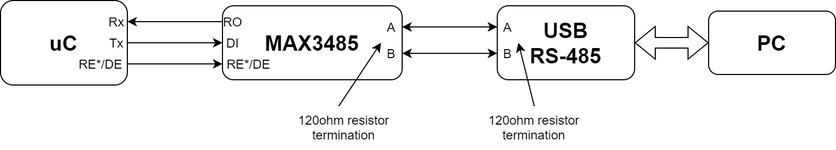
The main goal would be that the uC with MAX3485 can communicate with a PC with USD RS-485 adapter.

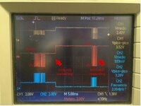
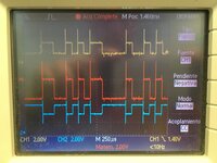
I attach 2 photos of oscilloscope. Yellow is signal A, Blue is signal B and Red is A-B
1) MAX3485 communicating with MAX485
2) MAX3485 communicating with USB RS-485. I attached a scheme of this too.

Any info would be appreciated.
Thanks!
 

Attachments

  • max3485 with USB RS-485.JPG
    max3485 with USB RS-485.JPG
    2.1 MB · Views: 337
  • max3485 with max485.JPG
    max3485 with max485.JPG
    1.8 MB · Views: 298
  • scheme.jpg
    scheme.jpg
    43.1 KB · Views: 287
Last edited:

Solution
The waveforms show USB-485 or MAX3485 transmitting? In any case, there's a problem with TxEnable. The sender is apparently switching between "space" (active state) and high Z. This is usually the case with "poor mans" RS-485 converters that are operating TxEnable by a monoflop rather than keeping it active during the full character frame by a dedicated TxEnable signal generated in the USB UART.

Getting the correct "mark" (idle state) level on RS-485 depends on the relation between pull-up/pull-down and terminating resistors. Using termination resistors without strong pull-up/pull-down resistors results in a differential level below receiver hysteresis and accidental received level.

Possible solutions:
- use strong (a few 100 ohms)...
Hi

Test each device individually and note the voltage levels.

Btw: I agree that RS485 should work with mixed supply voltage levels of 3.3 V and 5.0 V.

Klaus
 
The waveforms show USB-485 or MAX3485 transmitting? In any case, there's a problem with TxEnable. The sender is apparently switching between "space" (active state) and high Z. This is usually the case with "poor mans" RS-485 converters that are operating TxEnable by a monoflop rather than keeping it active during the full character frame by a dedicated TxEnable signal generated in the USB UART.

Getting the correct "mark" (idle state) level on RS-485 depends on the relation between pull-up/pull-down and terminating resistors. Using termination resistors without strong pull-up/pull-down resistors results in a differential level below receiver hysteresis and accidental received level.

Possible solutions:
- use strong (a few 100 ohms) pull-up/pull-down resistors to enforce idle state during driver high Z.
- for short cables (< 5m) and low or medium speed, remove 120 ohm termination resistors at both ends.
- use a state-of-the-art USB-to-RS485 bridge with active TxEnable. Wrong idle state (equals break signal) may be still a problem, depending on the receiver software.
 
  • Like
Reactions: ppr92

    ppr92

    Points: 2
    Helpful Answer Positive Rating
Solution
Hi

@FvM: how they are connected is shown in the picture´s name.

@ppr92:
After reading FvM´s post..
I´ve seen that the USB seems to cause the problem. It seems it´s never disabled.
Maybe there is some option (within PC driver setup, or ort setup) to automatically enable/disable the driver.
--> if there is a RS488 / RS485 option -> set it to RS485
--> if there is a full duplex / half duplex option -> set it to half duplex.

Klaus
 
Hi.

This is great! I tried what @FvM suggest as first possible solution. Connecting two 100ohms resistors (pull-up channel A + pull-down channel B) does the trick.
However, line seems a little bit unbalanced. I attached capture of oscilloscope and new scheme (sorry for the lazy scheme).
1) When neither devices is transmiting, signal A has a iddle state level of 2V and signal B of 1.2V. Plugging or unplugging the USB-485 doesn't affect. Any idea about this?
2) App note AN960 from analog devices (page 6) calculate the value of the pull-up pull-down resistor as a voltage diviver. For VCC = 3.3V the value I get is 930ohm but I get better results with 100ohm. Any comment about this?

Thanks!
--- Updated ---

Btw I saw that USB-485 has a texas instrument chip 75176B "SNx5176B Differential Bus Transceivers - datasheet"
(in case it helps)
 

Attachments

  • scheme.jpg
    scheme.jpg
    53.8 KB · Views: 307
  • MAX3485-USB485.jpg
    MAX3485-USB485.jpg
    138.4 KB · Views: 221
Last edited:

Hi
The shown resistors: 100R | 120R | 100R
Is not suitable.
The total resistance (termination should be 100...120Ohms
And the bias should result in more than +200mV

Try 500R | 120R | 500R

Klaus
 

    ppr92

    Points: 2
    Helpful Answer Positive Rating
Hi.

I tryed combination 220R | 150R | 220R. This allowed to elevate average value for difference A-B approx 400mV and still have an equivalent Rab = 110ohm. USB-485 works fine with this.

However, I think I going to change in my design MAX3485 to MAX3072E wich has true fail-safe implemented with a threshold of -50mV to 200mV.
Hope this works!

Thank you,
Pedro.
 

Hi,

The functional problem is not a resistor or termination problem.
I still agree with FvM that it´s a driver control problem.

***
I just wanted to point out that 120|100|120 Ohms is way off the expected 100...120Ohms differential resistance.

Klaus
 
I understand post #9 so that the connection is working. Exact termination resistor value doesn't actually matter for low speed, short distance link.
 

Hi,

The functional problem is not a resistor or termination problem.
I still agree with FvM that it´s a driver control problem.

***
I just wanted to point out that 120|100|120 Ohms is way off the expected 100...120Ohms differential resistance.

Klaus
Right.
Thing is that I don't know how the end user of this will use it. Hopefully will be a PLC or another controller with more sofisticated transceiver.
But should be prepare to work with this "Poor Mans" USB-485.

Anyway, first time working with RS-485.
Thanks!
 

Status
Not open for further replies.

Similar threads

Part and Inventory Search

Welcome to EDABoard.com

Sponsor

Back
Top