Continue to Site

Welcome to EDAboard.com

Welcome to our site! EDAboard.com is an international Electronics Discussion Forum focused on EDA software, circuits, schematics, books, theory, papers, asic, pld, 8051, DSP, Network, RF, Analog Design, PCB, Service Manuals... and a whole lot more! To participate you need to register. Registration is free. Click here to register now.

LTspice snubber simulations dont seem incorrect?

Status
Not open for further replies.

cupoftea

Advanced Member level 5
Joined
Jun 13, 2021
Messages
2,630
Helped
54
Reputation
108
Reaction score
116
Trophy points
63
Activity points
13,791
Hi,
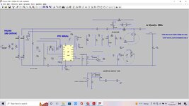
The attached is a 1000W Boost PFC sim in LTspice.......whether either or none of the ringed snubbers is connected up, makes virtually no difference to the voltage peaks on the diode and FET.
Why is this?
 

Attachments

  • 1000w PFC with snubbers.zip
    3.4 KB · Views: 175
  • 1000W Boost PFC with snubbers.jpg
    1000W Boost PFC with snubbers.jpg
    227.2 KB · Views: 214

Can you post the .asc file?
....Thats the .asc file in the top post, zipped up, the "attach link" wont take .asc files if not zipped.

I am actually wondering that the sim model of the FET does not account for the great reduction in Cds as Vds rises, and maybe thats why my fet blew up on the bench, since there was less capacitance than i thought to quell the drain node ringing.

I believe next time i power up this 1000w boost pfc, i will use only a 10uf cout, and a 1200v igbt, and a max duty cycle of 0.54 (thats as low as you cam make the max with ucc28070a)....and again only load it to 7W.

Another problem may be the distance i have from the 50:1 CST to the controller. Its a toss up whether to have the burden resistor near the CST , or near the controller....and whether to make the layout more complex by having dedicated "star" tracks from the CST to the burden resistor......thing is, the final cct is for 4 Boosters interleaved, so i want to keep the layout as simple as possible, as far as possible.
 

You can easily measure model capacitance. LTspice MOSFET model is using a simple function with few parameters and doesn't exactly model the capacitance according to datasheet exactly, but it gives at least a typical non-linear capacitance characteristic, see below. For better capacitance modelling you should refer to vendor models as provided e.g. by ST or Wolfspeed. Don't know if Rohm has it.

Total switching branch stray inductance should be rather in a 10 to 20 nH than several 100 nH order of magnitude, unless the PCB layout is really bad. Thus I doubt your simulation is realistic.

1659861359675.png
 

Attachments

  • MOSFET-cap.zip
    808 bytes · Views: 161

Status
Not open for further replies.

Part and Inventory Search

Welcome to EDABoard.com

Sponsor

Back
Top