vishweshgm
Member level 4

Hello,
I am designing a battery discharger that can discharge upto 200A on 100V. I want to allow user to configure discharge current configurable using pushbutton and LCD.
Here is my plan:

I plan to use tube resistors of 1200W,10ohm each in parallel so that for 100V it is capable to dissipate upto 250A. To control current A, I plan to use simple low side switching mosfet. I used a 5 PCB boards equipped with 2x 47A paralleled mosfets (total 5x2 = 10mosfets AND 5 driver chips MIC4422), so that for 200A, each mosfet will have 20A each, or 40A on each power PCB.
Power PCB schematic is as shown below. such PCBs and pwms are used. PWMs are given from another controller board that I have not shown.

Now my questions:
1. I set-up everything and given pwm from controller and all of a sudden controller board resets.
A close examination reveals that, on 3.3V supply (microcontroller supply), I am seeing a noise like this. This is happenign at mosfet switching off moment.
8V Max that you see is when only one mosfet board is being switched on, but it shoots upto 40V when multiple pwms on pcbs are turned on (which is my normal usecase). At this time controlller resets.
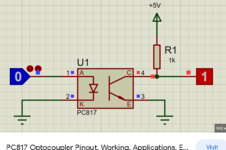
Here is the strage part, controller board grround (-ve of supply ) and battery-mosfet path ground is isolated using PC817 opto-coupler.

I am going crazy as this was absolutely not expected. when PWM is is isolated from controller supply, why does the controller supply pickup noise only when switching is running. Note that if I make pwm to be 0 or 100% there is no noise and controller runs properly. I elimineted issue in controller pcb by removing battery and running the switching pwm. This time there is no noise.
Also, my pwm frequency is only 50Hz, as I donot need mosfets to be switched fast for this application.
2. My second question is there any other easy low-cost way to achieve what I want? I am aware of using IGBT, yet it too has switching circuit which might result in same problem.
I am designing a battery discharger that can discharge upto 200A on 100V. I want to allow user to configure discharge current configurable using pushbutton and LCD.
Here is my plan:
I plan to use tube resistors of 1200W,10ohm each in parallel so that for 100V it is capable to dissipate upto 250A. To control current A, I plan to use simple low side switching mosfet. I used a 5 PCB boards equipped with 2x 47A paralleled mosfets (total 5x2 = 10mosfets AND 5 driver chips MIC4422), so that for 200A, each mosfet will have 20A each, or 40A on each power PCB.
Power PCB schematic is as shown below. such PCBs and pwms are used. PWMs are given from another controller board that I have not shown.
Now my questions:
1. I set-up everything and given pwm from controller and all of a sudden controller board resets.
A close examination reveals that, on 3.3V supply (microcontroller supply), I am seeing a noise like this. This is happenign at mosfet switching off moment.
8V Max that you see is when only one mosfet board is being switched on, but it shoots upto 40V when multiple pwms on pcbs are turned on (which is my normal usecase). At this time controlller resets.
Here is the strage part, controller board grround (-ve of supply ) and battery-mosfet path ground is isolated using PC817 opto-coupler.
I am going crazy as this was absolutely not expected. when PWM is is isolated from controller supply, why does the controller supply pickup noise only when switching is running. Note that if I make pwm to be 0 or 100% there is no noise and controller runs properly. I elimineted issue in controller pcb by removing battery and running the switching pwm. This time there is no noise.
Also, my pwm frequency is only 50Hz, as I donot need mosfets to be switched fast for this application.
2. My second question is there any other easy low-cost way to achieve what I want? I am aware of using IGBT, yet it too has switching circuit which might result in same problem.


