Continue to Site

Welcome to EDAboard.com

Welcome to our site! EDAboard.com is an international Electronics Discussion Forum focused on EDA software, circuits, schematics, books, theory, papers, asic, pld, 8051, DSP, Network, RF, Analog Design, PCB, Service Manuals... and a whole lot more! To participate you need to register. Registration is free. Click here to register now.

LNA design on ADS2009

Status
Not open for further replies.

husamsdu

Member level 1
Joined
Nov 1, 2012
Messages
38
Helped
3
Reputation
6
Reaction score
3
Trophy points
1,288
Activity points
1,493
Hello,

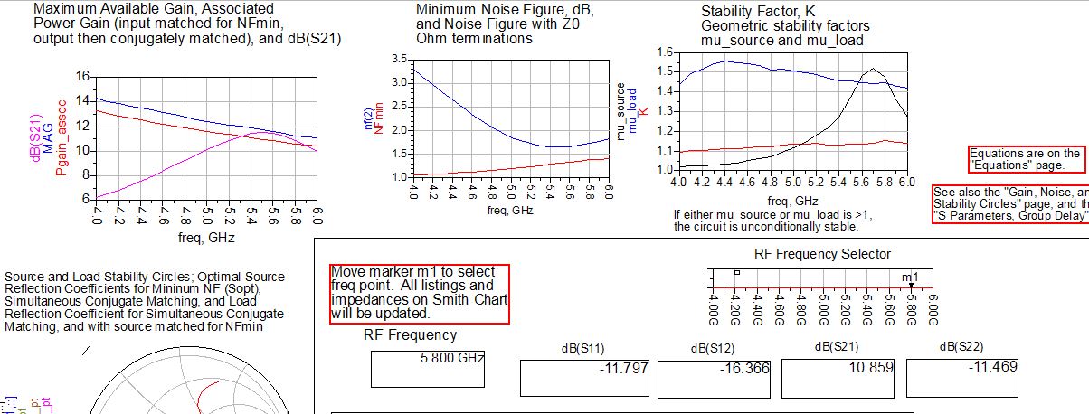
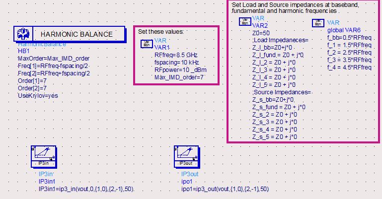
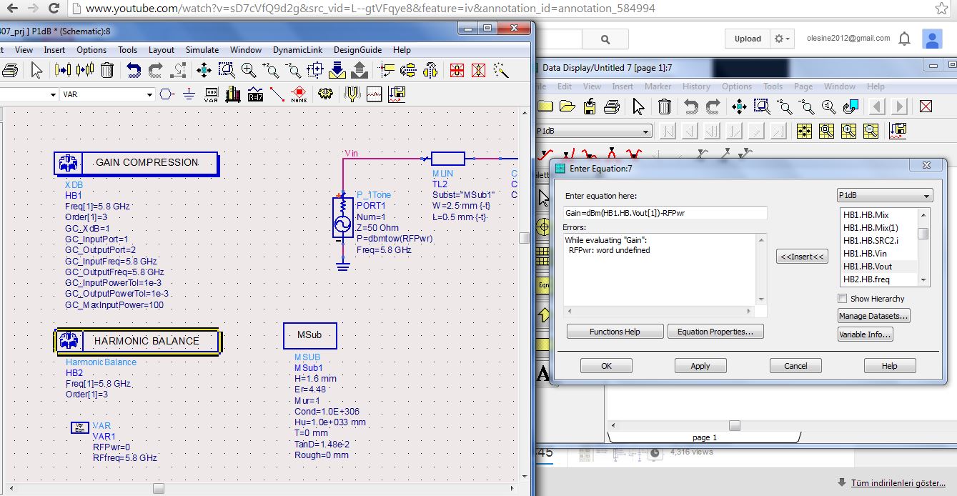
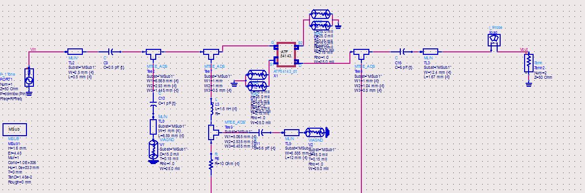
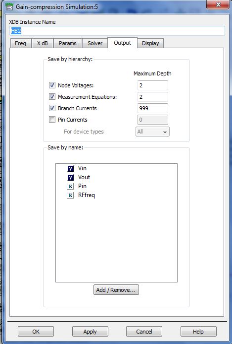
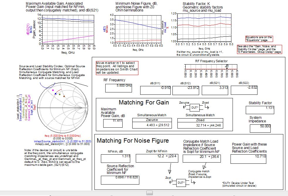
I designed an LNA working at 5.8GHz operating frequency. I simulate it on ADS2009. Here are the results.


I am new on ADS.I used AWR and got better results on AWR by changing microstripline dimensions of layout. Can i do this on ADS and how?

I want to get better results.

Thanks.
 

so many thanks guys. really i got some better values.Now i will make my schematic two stage.If i have any doubt i will ask you again.


Hello again.

I need to simulate Tone-1 and Tone-2. But first in Tone-1 i get this warning. I couldn't find it.

Can you help me?


Can you help me?

The text of the message tells you what the problem is: the geometry of your MTEE model is strange. The line widths are very different, and the electrical model for the MTEE is not designed for that extreme step in width. The MTEE model will not be accurate with these dimensions.

What can you do? Check if your layout looks correct. Usually, the MTEE line width are the same on both sides. If your case, they are very different. You can insert an MSTEP element to include the electrical effect of the step in width (from 8.29mm to 0.5mm).
 

1-DC simulation:OK
2-s-paramater simulation: OK
3-IIP3 & OIP3 simulation: Not OK

What is the wrong? I changed only RF freq. But it didn't work :(


What is not OK. It is difficult to tell without knowing more about the simulated/expected results. The common mistake made when doing any intercept point measurement is to be using an input drive power level that is too high. To measure intercept point the amplifier should be driven in the linear region of operation. If it is driven into or close to saturation then the assumptions in the calculation will not be correct and the results will be inaccurate.
 
What is not OK. It is difficult to tell without knowing more about the simulated/expected results. The common mistake made when doing any intercept point measurement is to be using an input drive power level that is too high. To measure intercept point the amplifier should be driven in the linear region of operation. If it is driven into or close to saturation then the assumptions in the calculation will not be correct and the results will be inaccurate.

Dear RealAEL,

it means i could not simulate OIP3 and IIP3. Results have nothing seen at the attachment.


You have not defined "vout". You need to add a named net at the required point in the schematic to make that measurement.
 
Dear RealAEL.

I want to simulate P1dB and IP3s. First i tried to simulate P1DB point . But i got an error while typing eqn. What can be wrong?


You are trying to create an equation that is effectively Gain=Pout(dBm)-Pin(dBm)

1. dBm(Vout) is not a power measurement but a voltage measurement. Power is voltage x current.
2. Variables like RFPwr do not automatically get added to the dataset to be available in the Data Display to be able to use it in an expression. Edit the HB Controller Output Tab and add RFPwr to the list of Save by name variable values prior to simulation.
 
Dear sir,

Really i have been trying for two weeks but i couldn't find what is wrong. i want to fiind P1dB point and then IP3 points. Please help.
document says gain=dBm(HB1.HB.Vout[1])-HB1.HB.Pin but there is no "HB1.HB.Pin" . what can i do?


You have defined Pin using a variable. Variable data will not be included in the simulation dataset automatically. You need to add it to the saved data. Edit the HB simulation controller and on the Output tab select Add/Remove... button at the botton and Add Pin data to the Current Selection list. Re-run the simulation and the data should become available.
 
I have already done it :( But there is no "HB1.HB.Pin" . Are there any different way to measure P1dB point?


If yo are sure that the variable data is being written to the simulation dataset but you do not see the data when reading a dataset from the Data Display then the two are different. Do you have multiple datasets in the project? Are you sure you are looking at the correct dataset?
 

i tried all datasets.

Also i tried sample PA.dsn and i pushed my circuit in it. when i simuate it gave me -162dB S21 value :(
 

Dear husamsdu:
I aslo have an exercise about design LNA with parameters: f= 2,4 GHz, B = 200 MHz, G >= 20dB, NF<=2 dB by ADS. But this is my first time using this software. My computer was installed ADS 2011. Can you show me your design (by ADS format), I can facsimile my Ex follow on yours. Tks so much.
 
Last edited by a moderator:

Status
Not open for further replies.

Part and Inventory Search

Welcome to EDABoard.com

Sponsor

Back
Top