Vermes
Advanced Member level 4
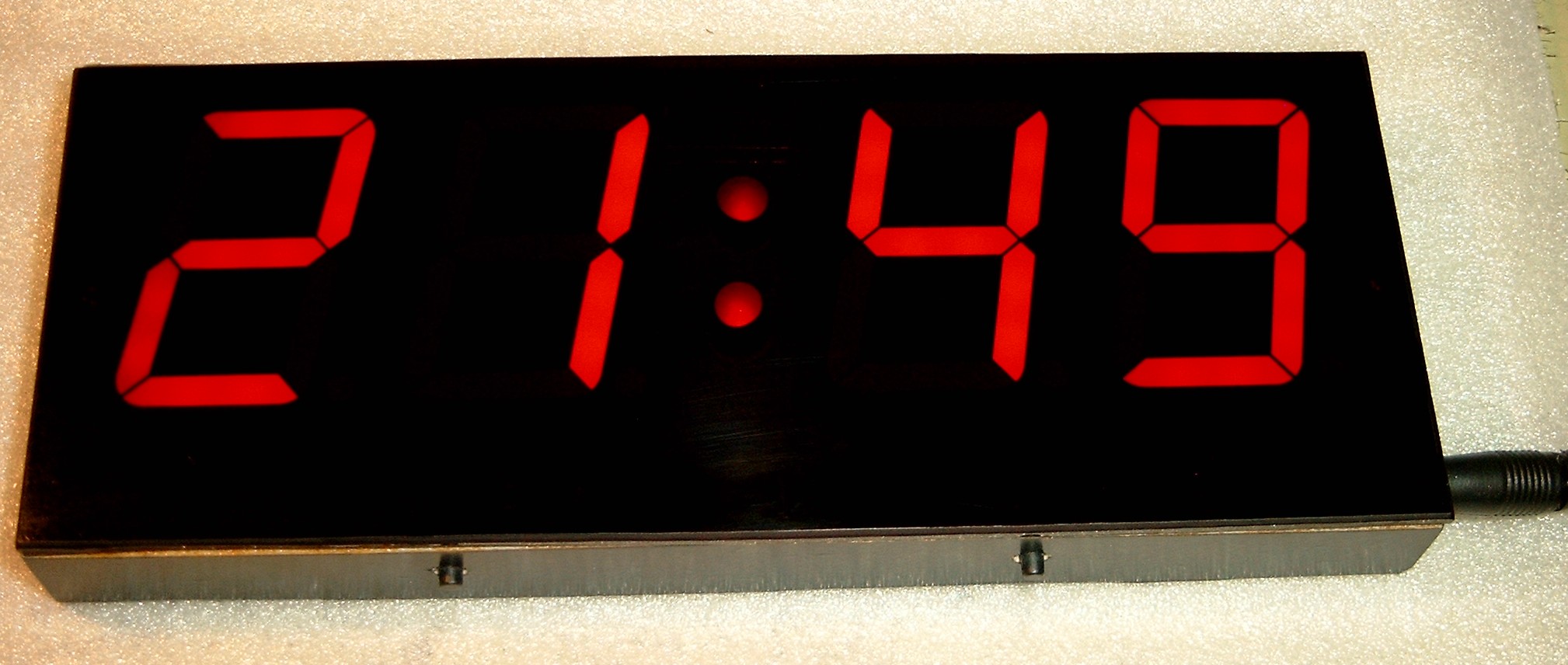
It is a big wall clock based on Atmega8. Its dimensions are: 180x70x18mm.
Presented clock displays not only hours and minutes, but also blinks the colon and has automatic control of the brightness depending on the lighting (the brighter the lighting is, the brighter the numbers are). In addition, it is equipped with programmable correction of the indication accuracy. Just set the correction to zero and set the time exactly (for example according to the DCF) and then leave the clock for a week, then compare the indication with the DCF. Correction value is the interval between successive acceleration or delay of the clock by 1 second, measured in 10 minutes periods.
To enter the correction input mode, turn the power off, press both buttons at once and still pressing them, turn the power on. The display will show „corr”, release the buttons and set the correction (hour decreases the value, min – increases). After 10 seconds from last button press, the clock saves the correction and returns to normal operation.
Note! A correction is stored in EEPROM, so after each programming, the processor should be set to -1. Do not forget to set it to 0 or calculated value after programming the processor.
How it looks inside:
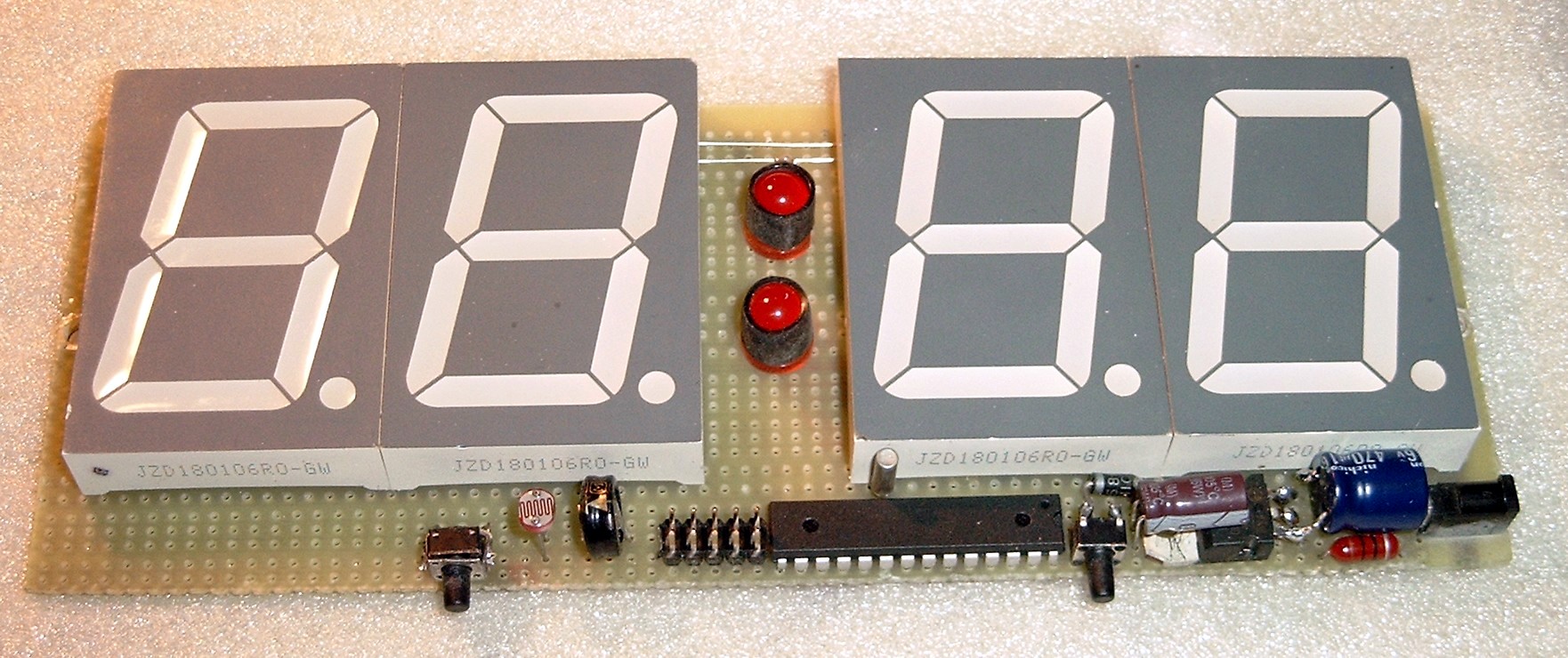
Displays consist of 1,8” (46mm) digits. They are relatively cheap, very bright, equipped with two diodes of diameter of 8mm. Displays have voltage drop at a level of 4V, so additional diode near the stabilizer 7805 was applied. Backup power was made of a GoldCap capacitor with a capacity of 0,22F, maintaining the processor power supply in the event of a power outage. The rest of the system is cut off by Schottky diode 1N5817 (or 1N5819).
Signal given to pin PC1 of the processor indicates the mains supply presence or absence, what causes disabling all the unnecessary systems and counting down the time. In that state, the processor consumes only 15uA, so such a GoldCap lasts for several - dozen hours without mains supply. The processor operates from internal RC generator set to 2MHz, and the clock quartz 32,768kHz connected to pins OSC1 and OSC2 drives Timer2 in asynchronous mode, which generates interrupts every second. After the processor reset (first run or too long loss of power), the clock shows „--:--” until the time setting.
Voltage divider with photoresistor is connected to PC0 (ADC0) port, and the internal A/D converter measures the voltage from that divider and respectively adapts the brightness of displays light using program PWM made with displays multiplexing. Photoresistor is connected to +5,6V, so the divider does not consume current from backup capacitor in the case of power failure. Capacitor 100n, which increases the processor resistance to interference (random resets) is connected to the RESET pin. Instead of SMD transistors (BC807), you can use BC327 (0,8A 50V).
The entire device is powered from a pulse charger for Nokia mobile phones. It gives approximately 9V.
PROG connector can be used for programming the processor and is in STK200 programmer standard. Software is written in C using a free compiler GCC in 3.4.5 version.
Schematic:
Link to original thread (useful attachment) – Kolejny zegarek LED na AtMega8, ale dokładny