Continue to Site

Welcome to EDAboard.com

Welcome to our site! EDAboard.com is an international Electronics Discussion Forum focused on EDA software, circuits, schematics, books, theory, papers, asic, pld, 8051, DSP, Network, RF, Analog Design, PCB, Service Manuals... and a whole lot more! To participate you need to register. Registration is free. Click here to register now.

Led tester design

Status
Not open for further replies.

Gaber Mohamed Boraey

Full Member level 2
Joined
Feb 26, 2015
Messages
149
Helped
4
Reputation
10
Reaction score
10
Trophy points
1,298
Activity points
2,249
Hello everyone
I need design simple led tester
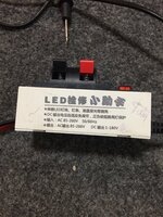
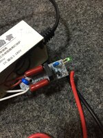
Like this one, but without voltage indicator screen, take a look


I need tester to test leds seperatly or in strips or on chips, simply for use to know if leds work or no,

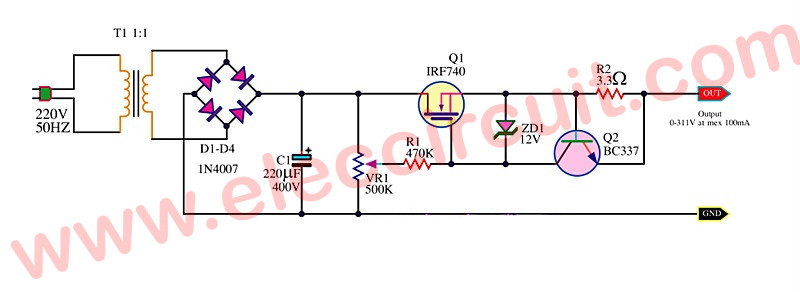
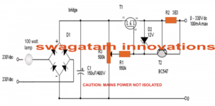
Need 220acv voltage supply
Voltage output from0-300v
The output current from30-50 ma
Output terminal to be safe of touching by user
Output voltage and current match the tested led and not to damage when tested in right direction or pppositte

I’m engineer but not electronic engineer, I mean I have good experience into electronics but not with design

Can anyone help me with the key to design this circuit?, what the scientific name so I can google or read about or anyone can help anyway?
Regards, thanks in advance
 

simple led tester
You can achieve some of your specs using a simple test circuit. However you need to invest funds and effort to achieve all specs.

As a start you construct a mains-powered supply, and adjust bias through a transistor acting as a variable resistor. Your led is the load. A couple of safety resistors keep current in a safe range.

The transistor requires heat sinking able to withstand upwards of 10 Watts.

You must know which direction to orient the led. A simple circuit cannot know if it's ruining the the led by overpowering the reverse breakdown voltage.
 
First thank you for your care to respond

You say:
As a start you construct a mains-powered supply, and adjust bias through a transistor acting as a variable resistor.

My question how connect transistor to act as variable resistor while there is main supply?, can you show similar circuit?
 

A very basic circuit with fixed current limiting.


Of a off the shelf start -


An approach using a Variac to adjust -


For safety I would advise you discuss with a power supply manufacturer for off the
shelf isolated supply.


Regards, Dana.
 
Last edited:

First thank you for your care to respond

You say:
As a start you construct a mains-powered supply, and adjust bias through a transistor acting as a variable resistor.

My question how connect transistor to act as variable resistor while there is main supply?, can you show similar circuit?

Send mains AC through a diode to create a single-polarity supply. (This avoids exposing the led to reverse voltage which might ruin it.)

Safety resistors are a good idea as shown below.
The 6.8k and the transistor must endure peaks of several Watts. The transistor may need heat-sinking. It must withstand 330V peak.

The usual limit for a plain led is 20mA. Keep an eye on your ammeter while dialing the potentiometer.
If you wish to add automatic current limiting then the circuit gets more complicated.

test setup 330 peak AC thru transistor adjust bias to test led.png
 
THanks brad

Is this variable voltage output ? , I mean if connect to one led like as to many leds?
The output voltage will not burn led?

Do you have any source help if need add automatic current limit?

Execuse me, the 500k potentiometer, to where connected that white dot?
 

Is this variable voltage output ? , I mean if connect to one led like as to many leds?
The output voltage will not burn led?

When testing a diode component, current change is more easily noticed than voltage change. For that reason we speak of current limiting for diode components (including led's and zeners). Such components automatically pull supply voltage to their threshold level. Of course too much current fries it.

Do you have any source help if need add automatic current limit?

Execuse me, the 500k potentiometer, to where connected that white dot?

The white dot shows that one leg of the potentiometer is disconnected.

House voltage is hazardous to work with. My schematic (post #5) exposes you to 220VAC if you touch a terminal. (A mere 1mA can stop your heart.)

Therefore it's wise to use a power supply at low voltage (say 20 or 30V) if you're testing low voltage led's. This classic current source is based on 2 NPN transistors. One layout has a plain red led. By choosing the proper resistor values it is always under 19mA.

Different color led's have different threshold voltages. This current source provides sufficient voltage to turn on any color led yet not expose it to more than 19mA.

The other layout has a 12V white led (which also can represent a string of led's adding up to 12V). It shows how reduced resistor value keeps it under 61mA.


simple current limiting 2 NPN (led's plain red and 12V white).png
 
Therefore it's wise to use a power supply at low voltage (say 20 or 30V)
I need 220v as supply for the circuit, need save money in components used
House voltage is hazardous to work with. My schematic (post #5) exposes you to 220VAC if you touch a terminal. (A mere 1mA can stop your heart.)
i know it’s dangerous, but never stopped my heart, I touched a lot before, don’t worry

I have at work led tester, only 3-4 resistors, two ceramic capacitor, and work great, providing from 1-180v , not sure how many ma, I need simple design like this

What you think of this attached circuit?
 

Attachments

  • 27A60F6E-B2DC-4EBC-A336-A54882999B10.png
    27A60F6E-B2DC-4EBC-A336-A54882999B10.png
    105.4 KB · Views: 371

Hi,

i know it’s dangerous, but never stopped my heart, I touched a lot before, don’t worry
Don't write such nonsense! I have to remind you that we are here in a public forum.
And there may be unexperienced users who read this and think 230VAC is not dangerous.

230V is dangerous!

For sure the lethality of 230V AC depends on a lot of parameters.
And also for sure many people already died by 230V AC.

Klaus
 
I reinforce Klaus's comments.

No isolation, no fuse, no AC safety standards, this is a product design that
is ready to kill people, kids, living things. Not valuing your life I get it, not
valuing others criminal.

Your lack of safety design is crazy dangerous attitude......

Regards, Dana.
 

Ok I understand, sorry for rush of me to comment on the 220v danger

Back to the design
What you think of this circuit?
Can it be used for led tester?
 

Attachments

  • A3A6D077-2297-4C37-B005-1971B959BFBA.png
    A3A6D077-2297-4C37-B005-1971B959BFBA.png
    105.4 KB · Views: 310

That’s very simple circuit , I need similar
That tester I work with everyday at work
I don’t want copy, just need similar design

Please look and advice
Regards
--- Updated ---

Hi,


Don't write such nonsense! I have to remind you that we are here in a public forum.
And there may be unexperienced users who read this and think 230VAC is not dangerous.

230V is dangerous!

For sure the lethality of 230V AC depends on a lot of parameters.
And also for sure many people already died by 230V AC.

Klaus
I am sorry
 

Attachments

  • 18337B37-1DB2-4335-8042-A0235624CC98.jpeg
    18337B37-1DB2-4335-8042-A0235624CC98.jpeg
    1.2 MB · Views: 196
  • E1D3C462-7FC6-4CBB-8AD7-BCF2ACF569F0.jpeg
    E1D3C462-7FC6-4CBB-8AD7-BCF2ACF569F0.jpeg
    1.3 MB · Views: 228

Hi,

Circuit of post#11:

Safety first: neither the one nor the other output is safe to touch.

Then:
* It will be hard to find a 300V+ rated pot
* I rather expect a 150mA current limit (so not "100mA max")
* you need to find a suitable fet for the voltage and power dissipation.
* and it needs a huge heatsink.

Klaus
This circuit without heat sink , and what I need, do you suggest any I can see?
 

Attachments

  • 107C6190-9567-4FBA-8AE1-CDF32FB74857.jpeg
    107C6190-9567-4FBA-8AE1-CDF32FB74857.jpeg
    1.3 MB · Views: 178

Status
Not open for further replies.

Similar threads

Part and Inventory Search

Welcome to EDABoard.com

Sponsor

Back
Top