Continue to Site

Welcome to EDAboard.com

Welcome to our site! EDAboard.com is an international Electronics Discussion Forum focused on EDA software, circuits, schematics, books, theory, papers, asic, pld, 8051, DSP, Network, RF, Analog Design, PCB, Service Manuals... and a whole lot more! To participate you need to register. Registration is free. Click here to register now.

LCD interfacing with Numato Spartan 6 fpga using Xilinx ISE

Status
Not open for further replies.

dheerajc

Newbie level 4
Joined
Nov 15, 2008
Messages
6
Helped
0
Reputation
0
Reaction score
0
Trophy points
1,281
Activity points
1,349
Hello all,
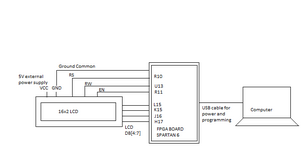
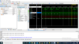
I have written a code in verilog for interfacing of 16x2 LCD with Numato Uno Spartan 6 FPGA board. Clock is 100 Mhz. However LCD is not even getting initialized. Can someone please tell me what is wrong with the logic.
Code:
module my_lcd(
input clk,
output reg rs,en,rw,                                 
output reg [7:4] LCD_out 
 );
 
 reg[7:0] count=0;
 reg [24:0] i=0;
 reg [7:0] char_data;
 reg [7:0] j;
 reg [24:0] num =0;

 reg [3:0] lcd_data;


 initial begin
           /* LCD Power ON Initialization time >15ms */
    rs=0;
    en=0;
    rw=0;
    Delay(2000000);    //20 ms delay   
 end
 
 always@(posedge clk)begin
 
 //if(count==10)count=0;
 case(count)
 0 : begin
 LCD_Command (8'h28);    /* Initialization of 16X2 LCD in 4bit mode */
 //    char_data = (8'h0F & 8'h28);
 //    LCD_out =   /*(LCD_out & 8'h0F) |*/  (char_data << 4);
 count <= count + 1'b1;   
 end
    
 1 : begin
 LCD_Command (8'h01);             //clear display screen
 //char_data = (8'h0F & 8'h01);
 //LCD_out = (char_data << 4);
 count <= count + 1'b1;   
 end     
 
 2 : begin
 LCD_Command (8'h02);           //Return home
 //char_data = (8'h0F & 8'h02);
 //LCD_out = (char_data << 4);     
 count <= count + 1'b1;   
 end     
 
 3 : begin
 LCD_Command (8'h0E);            //Display ON cursor blinking
//char_data = (8'h0F & 8'h0E);
//LCD_out = (char_data << 4);     
count <= count + 1'b1;   
 end     
 
 4 : begin
 LCD_Command (8'h0F);            //Display ON cursor blinking
//char_data = (8'h0F & 8'h0E);
//LCD_out = (char_data << 4);     
count <= count + 1'b1;   
 end   
 
 5 : begin
 LCD_Data(8'h48);                //'H'
//char_data = (8'h0F & 8'h0F);
//LCD_out = (char_data << 4); 
count <= count + 1'b1;   
 end   
 
 6 : begin
 LCD_Command (8'h14);            //Display ON cursor blinking
//char_data = (8'h0F & 8'h0E);
//LCD_out = (char_data << 4);     
count <= count + 1'b1;   
 end   
 
 7 : begin
 LCD_Data(8'h45);                //'E'
//char_data = (8'h0F & 8'h0F);
//LCD_out = (char_data << 4); 
count <= count + 1'b1;   
 end   
 
 8 : begin
 LCD_Command (8'h14);            //Display ON cursor blinking
//char_data = (8'h0F & 8'h0E);
//LCD_out = (char_data << 4);     
count <= count + 1'b1;   
 end   
 
 9 : begin
 LCD_Data(8'h4C);                //'L'
//char_data = (8'h0F & 8'h0F);
//LCD_out = (char_data << 4); 
count <= count + 1'b1;   
 end   
 
 10 : begin
 LCD_Command (8'h14);            //Display ON cursor blinking
//char_data = (8'h0F & 8'h0E);
//LCD_out = (char_data << 4);     
count <= count + 1'b1;   
 end   
 
 11 : begin
 LCD_Data(8'h4C);                //'L'
//char_data = (8'h0F & 8'h0F);
//LCD_out = (char_data << 4); 
count <= count + 1'b1;   
 end   
 
 12 : begin
 LCD_Command (8'h14);            //Display ON cursor blinking
//char_data = (8'h0F & 8'h0E);
//LCD_out = (char_data << 4);     
count <= count + 1'b1;   
end   

13 : begin
 LCD_Data(8'h4C);                //'L'
//char_data = (8'h0F & 8'h0F);
//LCD_out = (char_data << 4); 
count <= count + 1'b1;   
 end   
 
 14 : begin
 LCD_Command (8'h14);            //Display ON cursor blinking
//char_data = (8'h0F & 8'h0E);
//LCD_out = (char_data << 4);     
count <= count + 1'b1;   
end   

 15 : begin
 LCD_Data(8'h4F);                //'O'
//char_data = (8'h0F & 8'h0F);
//LCD_out = (char_data << 4); 
count <= count + 1'b1;   
 end   
 
 16 : begin
 LCD_Command (8'h14);            //Display ON cursor blinking
//char_data = (8'h0F & 8'h0E);
//LCD_out = (char_data << 4);     
count <= 1'b1;   
end     
 
default : LCD_Data(8'h48); //By default display 'H'
  
 endcase
 end


////
task LCD_Command (input [7:0] j);
begin
    rs=0;            /* Command reg. */
    Delay(100000);  //1 ms delay
    rw=0;   
    Delay(100000);
      
    //LCD_out = (LCD_out & 8'h0F) |(j & 8'h0F);//(LCD_out & 8'h0F) |(j & 8'hF0);/* Send upper nibble */
    LCD_out = ( j & 8'hF0);
            /* Write operation */
    en=1;
    Delay(500000);
    en=0;
    Delay(500000);
    
    LCD_out =   /*(LCD_out & 8'h0F) |*/ (8'hF0)&(j << 4);/* Send lower nibble */
    en=1;            /* Enable pulse */
    Delay(500000);
    en=0;
    Delay(500000);
end
endtask

//
task LCD_Data (input [7:0] char_data);

begin
    rs=1;              /*Data reg.*/
    Delay(100000);
    rw=0;              /*Write operation*/
    Delay(100000);
    //LCD_out = (LCD_out & 8'h0F) | (char_data & 8'h0F);//(LCD_out & 8'h0F) | (char_data & 8'hF0);/* Send upper nibble */
    LCD_out = ( char_data & 8'hF0);
    en=1'b1; 
    Delay(500000); //5 ms delay
    en=1'b0;
    Delay(500000); //5 ms delay

    LCD_out = /*(LCD_out & 8'h0F) |*/ (8'hF0)&(char_data << 4);/* Send lower nibble */
    en=1'b1;              /* Enable pulse */
    Delay(500000);  //5 ms delay
    en=1'b0;
    Delay(500000);  //5 ms delay
end
endtask

task Delay (input [24:0] i);
begin
    if(num == i) num =0;
    else num = num + 1;   
end
endtask

endmodule

And this is the constraint file.
Code:
NET "clk" LOC = V10;   //100 Mhz clock
NET "rs"  LOC = R10     | IOSTANDARD = LVCMOS33 | DRIVE = 8 | SLEW = FAST ; #Pin 3    //P8
NET "en"     LOC = R11     | IOSTANDARD = LVCMOS33 | DRIVE = 8 | SLEW = FAST ; #Pin 1    //P8   
NET "rw"  LOC = U13     | IOSTANDARD = LVCMOS33 | DRIVE = 8 | SLEW = FAST ; #Pin 5    //P8

//NET "LCD_out[0]" LOC = H17    ;  //| IOSTANDARD = LVCMOS33 | DRIVE = 8 | SLEW = FAST ; #Pin 1    //P9
//NET "LCD_out[1]" LOC = J16    ;  //| IOSTANDARD = LVCMOS33 | DRIVE = 8 | SLEW = FAST ; #Pin 3    //P9
//NET "LCD_out[2]" LOC = K15    ;  //| IOSTANDARD = LVCMOS33 | DRIVE = 8 | SLEW = FAST ; #Pin 5    //P9
//NET "LCD_out[3]" LOC = L15    ;  //| IOSTANDARD = LVCMOS33 | DRIVE = 8 | SLEW = FAST ; #Pin 7    //P9

NET "LCD_out[4]" LOC = L15     ;  //| IOSTANDARD = LVCMOS33 | DRIVE = 8 | SLEW = FAST ; #Pin 1    //P9
NET "LCD_out[5]" LOC = K15     ;  //| IOSTANDARD = LVCMOS33 | DRIVE = 8 | SLEW = FAST ; #Pin 3    //P9
NET "LCD_out[6]" LOC = J16     ;  //| IOSTANDARD = LVCMOS33 | DRIVE = 8 | SLEW = FAST ; #Pin 5    //P9
NET "LCD_out[7]" LOC = H17     ;  //| IOSTANDARD = LVCMOS33 | DRIVE = 8 | SLEW = FAST ; #Pin 7    //P9
 

Hi,

All this to me looks more like software than a hardware description.

Are you aware that HDL code runs "in parallel" and not sequentially (like software)?

You give no hint about the problem ... and you don't show simulation results, thus we don't know what to look for.
Thus please answer some questions:

Did you run a simulation of your project?
Do you have a scope to verify the signals?
Did you do some debugging on your own? What are the results?
Did you write the code "all at once" or did you do step by step coding and testing?
Did you even test if your delay function works like expected?

Are you sure your display can work with 3.3V (supply) levels?
And please show a schematic... (hand drawn is O.K.)

Klaus
 

Hi klausST,
Thanks for the reply.
1) My problem is nothing is appearing on LCD. I tried to write code in various ways. Without using tasks, used for loop for delay, sent only commands and no data. Sent commands and only single character. However black boxes are still there on LCD, which i think is an indication that LCD is not even initialized with sent commands.
2) I tried code code posted on Github for Numato board. Even that too is not executed.
3) Then i tried this
**broken link removed**
This code is working.
4)Yes I ran simulation.
5) I don't have a scope.
6) Yes i am aware that HDL runs in parallel.
7) I tried to debug. Reached on a conclusion that 'Task' is not getting called up. LCD port data is not getting updated. Value is not getting passed to 'Task Delay' It may be because i wrote it in a wrong way.
8) LCD is powered up with external 5V adapter.
9) I have just started working on HDL languages. I know there is a problem in coding. But couldn't get where the problem lies exactly.

PLease let me know if i answered all your questions.
 

Attachments

  • LCD_FPGA_Connections.png
    LCD_FPGA_Connections.png
    8 KB · Views: 210
  • LCD_Simulation.png
    LCD_Simulation.png
    155.1 KB · Views: 175

Hi,

you said you ran a simulation. But this is only half the way. You additionally need to validate the simulation results.

You show a simulation screen:
* the whole window shows about 130ps of time.This makes no sense at all.
* CLK shows a full wave every 10ps... this equals to a frequency of (did you calaculate it on your own?) 100GHz!!!
* did you notice that the RS timing is far from being meaningful? (even not with a correct CLK frequency)
* since the CLK shows ideal timing, I guess you did not use device specific constraints.

Did you read the datasheet of the (to us unknown) display?

I guess you use a HD44780 compatible display.
Your simulation runs for 1ms. But even the "Return Home" command is specified to take 1.52ms.

******
My recommendation:
Start with much easier projects. Read turorials (or watch video tutorials) how to write HDL, how to use the simulation tool.
Start with blinking a LED. Then add another LED with different blink frequency.
**
Generate meaningful clocks (indeed clock_enables) for your display. Verify them.
Then generate the display_EN signal. Verify it
Then write a state machine for display access. Then generate RS and RW signals. Verify them.
Then write static data. Verify it
Then write a state machine for display initialisation...Verify it
... and so on. Step by step.

Nobody of us did write a whole "display control unit" as first project.

Klaus
 
Your 100 GHz clk makes little sense, but the frequency must not necessarily matter in a functional simulation.

The basic problem of your code is the inappropriate usage of tasks. You can have timing functions in a task, e.g. clock events, but then the task must not be called inside clocked sequential code.

You can see in your simulation that the Delay task isn't working as expected. It's increasing num by 6 once per LCD_command or LCD_data call, but it's not waiting for anything. As no design output depends on the register num, it's eliminated in synthesis.
3) Then i tried this
**broken link removed**
This code is working.
Did you try to find out why?
 

Code Verilog - [expand]
1
2
3
4
5
6
7
initial begin
           /* LCD Power ON Initialization time >15ms */
    rs=0;
    en=0;
    rw=0;
    Delay(2000000);    //20 ms delay  
end


This doesn't do anything for power on initialization time as the delay doesn't exist anywhere but in a simulation. Depending on the FPGA technology the initial block may not even do anything for setting rs, en, or rw to 0 (only devices that have some sort of power on loading of registers in the device would be able to initialize those values.

The hardware approach is to use a reset input to reset registers to the correct initial values after power up of device and to generate delays you use a counter that counts 20 ms of delay, i.e. 0-1999999.
 
Hi,

you said you ran a simulation. But this is only half the way. You additionally need to validate the simulation results.

You show a simulation screen:
* the whole window shows about 130ps of time.This makes no sense at all.
* CLK shows a full wave every 10ps... this equals to a frequency of (did you calaculate it on your own?) 100GHz!!!
* did you notice that the RS timing is far from being meaningful? (even not with a correct CLK frequency)
* since the CLK shows ideal timing, I guess you did not use device specific constraints.

Did you read the datasheet of the (to us unknown) display?

I guess you use a HD44780 compatible display.
Your simulation runs for 1ms. But even the "Return Home" command is specified to take 1.52ms.

******
My recommendation:
Start with much easier projects. Read turorials (or watch video tutorials) how to write HDL, how to use the simulation tool.
Start with blinking a LED. Then add another LED with different blink frequency.
**
Generate meaningful clocks (indeed clock_enables) for your display. Verify them.
Then generate the display_EN signal. Verify it
Then write a state machine for display access. Then generate RS and RW signals. Verify them.
Then write static data. Verify it
Then write a state machine for display initialisation...Verify it
... and so on. Step by step.

Nobody of us did write a whole "display control unit" as first project.

Klaus
Thanks for your feedback sir. I have done blinking LED with different frequencies. Seven segment display. However i needed directions as to in what directions i need to work on for this project though i have interfaced LCD with microcontroller using embedded c. But HDL happened to be a completely different job. I will follow the steps you suggested. I still wonder why values are not getting passed to 'Delay Task'. And why 'EN' signal is getting active or why LCD_out port not getting any values. Means, my program logic could be wrong but at least values should have passed.
 

Your 100 GHz clk makes little sense, but the frequency must not necessarily matter in a functional simulation.

The basic problem of your code is the inappropriate usage of tasks. You can have timing functions in a task, e.g. clock events, but then the task must not be called inside clocked sequential code.

You can see in your simulation that the Delay task isn't working as expected. It's increasing num by 6 once per LCD_command or LCD_data call, but it's not waiting for anything. As no design output depends on the register num, it's eliminated in synthesis.

Did you try to find out why?
Yes sir. i tried to find out. However didn't get it as to why. So decided to write it on my own in whatever possible ways. I am doing this since last 2 and half months or so. I think i need to work on it more.
--- Updated ---


Code Verilog - [expand]
1
2
3
4
5
6
7
initial begin
           /* LCD Power ON Initialization time >15ms */
    rs=0;
    en=0;
    rw=0;
    Delay(2000000);    //20 ms delay 
end


This doesn't do anything for power on initialization time as the delay doesn't exist anywhere but in a simulation. Depending on the FPGA technology the initial block may not even do anything for setting rs, en, or rw to 0 (only devices that have some sort of power on loading of registers in the device would be able to initialize those values.

The hardware approach is to use a reset input to reset registers to the correct initial values after power up of device and to generate delays you use a counter that counts 20 ms of delay, i.e. 0-1999999.
Thanks sir.
So do coding style depends upon the FPGA technology. I think this is going to be very tough. Can you please give one such example where a delay of any time period is generated using 'Task'
--- Updated ---

Your 100 GHz clk makes little sense, but the frequency must not necessarily matter in a functional simulation.

The basic problem of your code is the inappropriate usage of tasks. You can have timing functions in a task, e.g. clock events, but then the task must not be called inside clocked sequential code.

You can see in your simulation that the Delay task isn't working as expected. It's increasing num by 6 once per LCD_command or LCD_data call, but it's not waiting for anything. As no design output depends on the register num, it's eliminated in synthesis.

Did you try to find out why?
Sir if i may ask, can you please tell why Delay task is not working. Why it is not waiting for anything. Are any vales getting passed to any of the Tasks. I think no.
 
Last edited:

Hi,

Forget about microcontroller, forget about software.
Don't think in code lines processed one after the other. Don't think in "tasks" processed as subroutines.
Don't think in "values to get passed"

Think as schematic. Logic gates, counters, flip flops, MUXes....

I still wonder why values are not getting passed to 'Delay Task'. And why 'EN' signal is getting active or why LCD_out port not getting any values. Means, my program logic could be wrong but at least values should have passed.
My ideas to your text:

I don't see EN to get active. Where do you see this?
How can you say LCD_out port does not get any values? With a simulation time of 1ms you simply don't have a chance to verify this.
Don't call it "program".
When you say "pass data" ... this means to "multiplex data" onto a bus to a DFF .. then activate the "clock_enable" of the according DFF ..and prevent "clock_enable" from being activated as long as you need the data to be kept in the DFF.

Klaus
 

Hi,

Forget about microcontroller, forget about software.
Don't think in code lines processed one after the other. Don't think in "tasks" processed as subroutines.
Don't think in "values to get passed"

Think as schematic. Logic gates, counters, flip flops, MUXes....


My ideas to your text:

I don't see EN to get active. Where do you see this?
How can you say LCD_out port does not get any values? With a simulation time of 1ms you simply don't have a chance to verify this.
Don't call it "program".
When you say "pass data" ... this means to "multiplex data" onto a bus to a DFF .. then activate the "clock_enable" of the according DFF ..and prevent "clock_enable" from being activated as long as you need the data to be kept in the DFF.

Klaus
My apologies. I wanted to say 'EN' not activated. When 'RS' can get high, low may be in haphazard manner, then why not 'EN'. I ran simulation even for 10ms, however result remains same. I really need to get into it.
 

Status
Not open for further replies.

Part and Inventory Search

Welcome to EDABoard.com

Sponsor

Back
Top