Continue to Site

Welcome to EDAboard.com

Welcome to our site! EDAboard.com is an international Electronics Discussion Forum focused on EDA software, circuits, schematics, books, theory, papers, asic, pld, 8051, DSP, Network, RF, Analog Design, PCB, Service Manuals... and a whole lot more! To participate you need to register. Registration is free. Click here to register now.

LCD and pic not comunication

Status
Not open for further replies.
In my opinion, MikroC debugging is next to useless. I doubt it will prove anything.
Agreed but the OP has only just started to show that his hardware is 'capable' of running and my suggestion to use the debug mode was simply to ensure the code was actually executing. Also it would have the advantage you were talking about of introducing a (big) delay after power on and perhaps show up a timing issue.
It probably wouldn't help beyond that.
Susan
 

Hello

LCD problem normally occurs when you forget to configure the clock frequency.

Use the OSCCON or equivalent register at the start of your main() to set the proper clock source. Then from the Project menu, select Edit Project. It will open the configurations. From Oscillator Selection, select the proper oscillator that you want to use. Also set the MCU Clock Frequency on the right side.
Click OK and rebuild your project.


For example, if you are not using any external oscillator, use the following settings with the internal oscillator for PIC16F628A:

OSCF_bit = 1; // using 4 MHz internal oscillator <-- write this as the first line after main()

Then in the configurations, select INTOSC oscillator: IO function on RA6
Set the clock as 4 MHz on the right side.


I hope this helps.
 
Last edited:

^ That was just an example. In either case, they have to select the proper configuration bits, otherwise mikroC will not generate proper timing signals for the LCD.
 

I try anithing you say and nothing:(.I don't know what to do :((.Why is not working?What i doing wrong:(.Can anyone send me a good schematic and a good code from this pic in who from him is worked?Plese,i don't know why is not worked!From a month i still try and nothing:(
 

Zip and post your mikroC PRO PIC project files. I will check it once. What frequency Crystal are you using ?
 

I ipload miKroC program above.Thx you verry much Okada.I don't know why is not worked:((.I used 4 MHZ quartz oscilator with 22pF capacitor.I put on decoupling cap between VDD and VSS with 100nF and still nothing:(
 

Attachments

  • LCD Interfacing PIC - MikroC.rar
    18 KB · Views: 97

Try wiring the LCD data lines as in the examples. It may be that MikroC expects them to be in the top or bottom four bits of the port. You have them wired to bits 5, 4, 3 and 2 which the library may not support.

Just a guess - I use a different compiler.

Brian.
 

I put on decoupling cap between VDD and VSS with 100nF and still nothing:(

Only a single 0.1uF decoupling cap, what about a lower frequency decoupling cap? At a minimum you should have both a 10uF and 0.1uF decoupling to start as was stated in post #20.
 

You have used RB2 for both Enable and D7

Code:
// LCD module connections
sbit LCD_RS at RB1_bit;
sbit LCD_EN at RB2_bit;
sbit LCD_D4 at RB5_bit;
sbit LCD_D5 at RB4_bit;
sbit LCD_D6 at RB3_bit;
sbit LCD_D7 at RB2_bit;
You cannot do that...
 

I had a quick look at your C code file (lcd4.c) and it is missing a key feature of any embedded program: the 'while' loop.
An embedded program is expected to run forever and the 'main' function should never return. After all, there is no'operating system' for the program to return to when it finishes.
I don't know about the mikroC computer but other compilers I have used create small runtime initialisation code that sets up things such as the initialised global variables, stack pointers etc and then calls the 'main' function. If the 'main' function does ever return, the compilers that I've used have that runtime code perform a reset that restarts the device all over again.
What *might* be happening is that the LCD initialisation code takes a littler bit of time to run and shows a blank LCD display while it does. Your code then writes a line to the display but then immediately the main exits and the device resets, causing the LCD initialisation code to blank out the display again. If this happens fast enough, then your eye will not see the LCD output and so the device will appear to be not working.
Just a guess.....
Susan
Sadly you guess wrong. mikroE compilers effectively put an infinite loop at end of your program whether you remember to provide your own loop or not.

I prefer to see code with the loop included, but it is not essential while using mikroE compilers.

The attached project in post #27 works fine if you change LCD_Enable pin to RB6 in pin definitions (and hardware)
 

I checked out the 'lcd4.lst' file in the .rar file in post #27. At the end of the 'main' function there is a 'goto $+0' (address 0x0121). Address 0x0000 has a 'goto 257' instruction. Address 0x0101 has the label '_main:' above it and what looks like setup code that falls into the user-written code at address 0x011a.
The first instruction there is the call to 'Lcd_Init'.
Therefore the problem I mention of continuous initialisation of the LCD will be occurring - however it would appear that the duration the display is showing the characters is long enough to be seen.
Susan
'goto $+0' at the end of the main function means "loop self" and prevents exit to (non-existent) operating system. It does NOT mean goto address zero.

LCD_Init() is only called once in this program
 
Last edited:

Try this. I modified the code a little. As mentioned by hexreader you have to change the pin connection used for LCD_EN or LCD_D7. I have made that change in the code. Before making changes I compiled your code and saw differences in the generated .hex file. I guessed you had compiled the code before posting it here. If yes, then there is really a problem with the Compiler. Open my C code but do not compile it. Just make new connections for LCD as I have defined and then burn my .hex file and check on hardware. If LCD works then problem is with Compiler.
 

Attachments

  • LCD Interfacing PIC - MikroC.rar
    17.9 KB · Views: 75

Ok,thx you verry much.I will do that soon i reache home and i will tell you the behavior.I hope that would be the problem.Thx you verry much!

- - - Updated - - -

I make this experiment:I make a program with arduino and arduino LCD shield and send "Hello" on LCD.It's works only if i used the same VDD and VSS from arduino board.If i connect separated board on arduino,and connect VDD and VSS of shield an another source by arduino is not work,show some randon character on LCD,but if i take than source by arduino it's worked.

Then i make the same experiment but now with my 2 different LCD,and in both cases it's not worked,just see random characters on LCD.

Then I take the arduino LCD shield and connect to PIC and use the same VDD and VSS,and nothing was happened,even see random character.First row of LCD just stay lights.

I don't know what is fappened.Now i'm shure that the LCD shield is work fine,but i don't understand when i make the exeperiment with arduino with other 2 simple LCD why it's not work,why just show me a random character and not what i send "Hello".I connected them in the same way how i connected the LCD shield...
 

Using two power sources always causes problems and I would not advise you do it unless you are fully aware of the problems it can cause.

If you power the LCD before the PIC, you apply reversed voltages to the PIC because the LCD pull-up components try to make the PIC pins adopt a higher voltage than its VDD pin. If you power the PIC before the LCD, the reverse happens and you also face sending the initializing commands to the LCD before it is ready to accept them.

Whatever you do, ALWAYS make sure the VSS of both sources are firmly connected together, even if the power is turned off. Failing to do so will almost certainly damage one or the other component.

Brian.
 

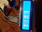
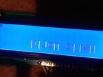
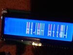
Hy Okada,hy all,i try Okada code and first time was the same result.After that i connect LCD and PIC at the same VDD and VSS.And first time i power the PIC and reflash,and than i open the LCD bot still nothing.Finnaly i remove PIC cnnection from LCD and judt reflash him lonly,separate from LCD,and then connect LCD and power on,and surpise it's work.:D.FINALLY work.But this is happened with LCD arduino shield.I try the same method with my 2 different LCD and something works,but not some good.I atache some pics with result.The problem now is when i adjust more the LCD pin 3 (VD),to see more or less the character with a 10k,100k,trimmer potentiometter the result can see in the picture.This behavior is meet only on my LCD.On LCD arduinoshield the behavior is just ok.What is wrong now?

20161214_192543.jpg20161214_192622.jpg20161214_192626.jpg
 

'goto $+0' at the end of the main function means "loop self" and prevents exit to (non-existent) operating system. It does NOT mean goto address zero.
Long time since I did assembler and it was for a completely different architecture - I stand corrected.
Susan
 

Code:
goto $+1
means Go to next instruction.

$+0 = loop here only.
 

Status
Not open for further replies.

Similar threads

Part and Inventory Search

Welcome to EDABoard.com

Sponsor

Back
Top