Continue to Site

Welcome to EDAboard.com

Welcome to our site! EDAboard.com is an international Electronics Discussion Forum focused on EDA software, circuits, schematics, books, theory, papers, asic, pld, 8051, DSP, Network, RF, Analog Design, PCB, Service Manuals... and a whole lot more! To participate you need to register. Registration is free. Click here to register now.

LC filter design for converter

Status
Not open for further replies.
More detail info for the required converter -
Ripple voltage = 1%
Ripple current =10%
Full load = 1A (load for this converter will be an bridge inverter, final load can be inductive with pf 0.7)


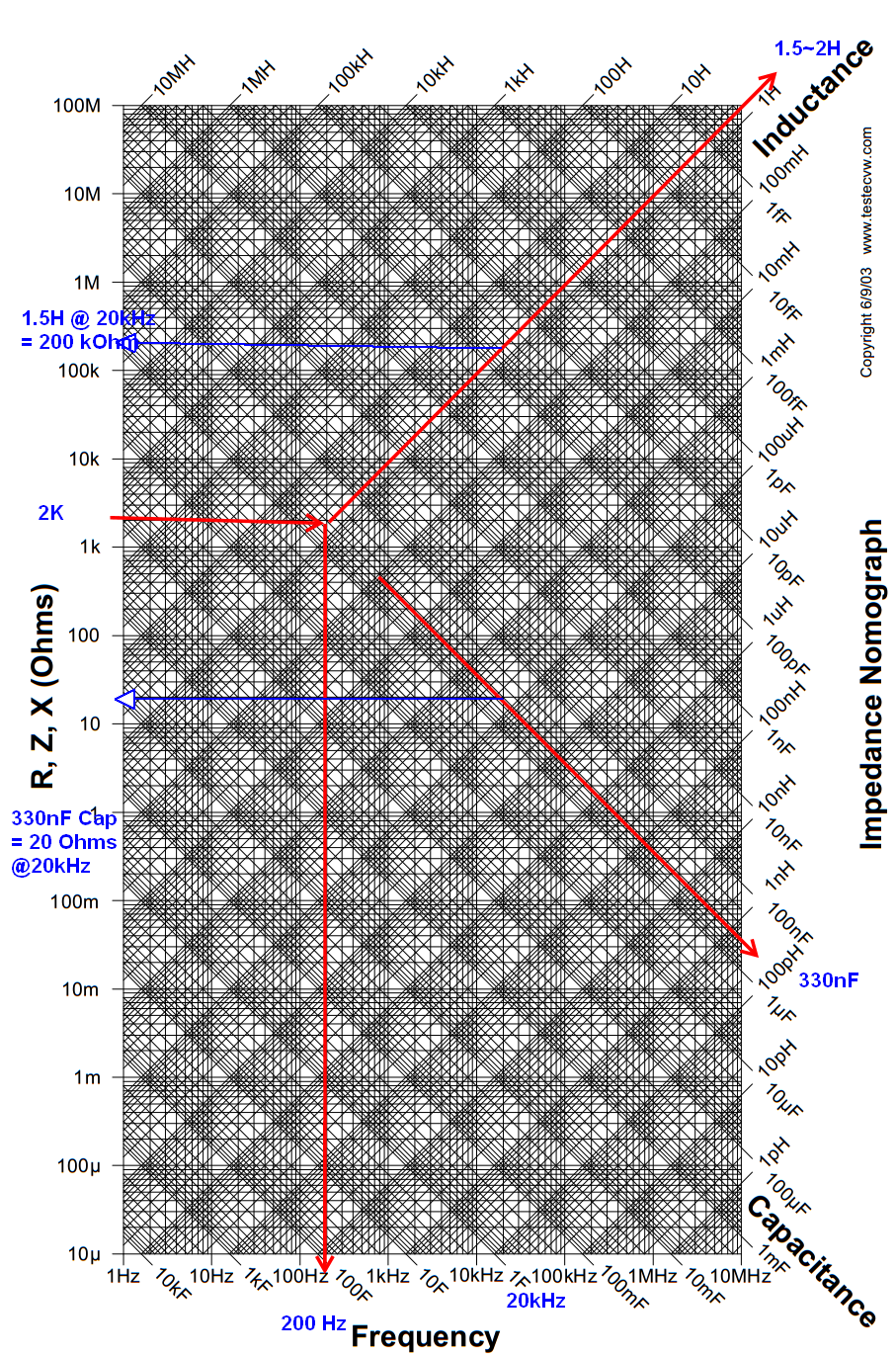
This is not meant to be a solution to your homework, but rather a quick visual example of a handy nomograph. You can read PF from this as well from tan^-1(reactance/resistance) ratio approximations..maybe

You can design 1st order RC or 2nd order LCR filters either LPF, HPF, BPF, , with attributes such as Q and determine attenuation by known impedance ratio. from breakpoint to checkpoint or gain with Q being X/R for series resonant and R/X for parallel resonant. and X=R intersection for Q=1.


You can read the impedance of any reactive part at an frequency at a glance and considering accuracy of reactive partis often adds up to 10% this is similar to tolerance reading the graph. Good eyes and skill can estimate to 5%.

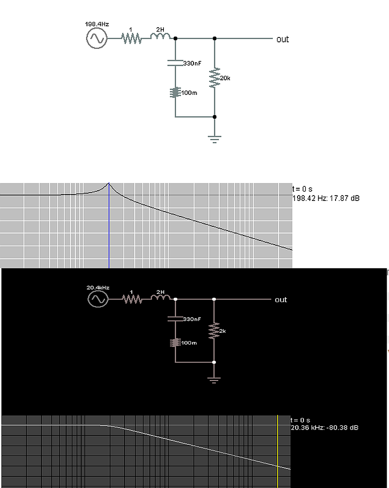
here is a 200 Hz filter. Chosen for a Q=1 at 200 Hz @ 2k Ohm
3414643600_1418281034.png

Now look up the values of LCR that intersect at 200 Hz which are the same I used above.
The impedance of 2K is flat with a Q=1 and vs 20K the Q=10 so the gain minus realistic ESR losses is almost 20dB and the loss 1 decade up is 40dB 2 decades up at 20kHz is 80dB.

Impedance ratio on nomograph quick lookup says the same.
8572704300_1418282326.png


Now to design a filter choose the same parameters for worst case load source impedance and attenuation and Q and choose the intersecting values.

Impedance ratios of ESR for L RdsOn and Cap combine to limit current ripple but with L impedance swamps this so the current ripple is the ratio of impedance of ESR/XL(f) for series circuits. while the voltage ripple is Xc(f) / R(load)


This whole exercise is just that practise.

Real design starts with a good spec, a block diagram and a clear description of the functions.
 

Attachments

  • LCR.png
    LCR.png
    748.3 KB · Views: 74

Re: LC filter design for converter
More detail info for the required converter -
Ripple voltage = 1%
Ripple current =10%
Full load = 1A (load for this converter will be an bridge inverter, final load can be inductive with pf 0.7)
Still unclear if the output inverter is square wave or sine pwm.
 

Still unclear if the output inverter is square wave or sine pwm.

Now I'm only talking about on thre first stage -

12v dc----> 336v dc

the output will be dc only. Need calculation for LC filter for this stage.

I've mentioned inverter for the load of the converter. Inverter is planned to be SPWM.
 

I've found an application note (AND9135/D) from ON Semiconductor describing designing of LC filter for Buck converter. Reading the document it seems to me that the technique of getting the value of the inductor (L) and capacitor (C) for LC filter from the buck converter output waveform can be applied for bridge converter as well. Is my understanding correct?

Formula to calculate L and C for LC filter given in the document is -
L= (Vm-Vout)*D/(LIR*Iout-max*fsw)
Cmin=L*Lpk^2/((Vov+Vout)^2-Vout^2)

for my case,
Vm=400v (peak value of the transformer output)
Vout= 326v (required output dc voltage)
LIR=0.15A (inductor ripple current ratio; 15% ripple for 1A load)
Iout-max=1A (max output current)\
fsw=80kHz*2=160kHz (for my bridge converter output)

L=2.466mH
I can consider 3mH

Using the formula for C, required capacitance value is 0.325uF. I can use 0.47uF; I have used 1uF non electrolytic ceramic capacitor having rating 600v.

AND9135/D
https://www.onsemi.com/pub/Collateral/AND9135-D.PDF
 

Yes, 12 to 326v dc.
I'm doing with square wave only.
 

for my case,
Vm=400v (peak value of the transformer output)
Vout= 326v (required output dc voltage)
LIR=0.15A (inductor ripple current ratio; 15% ripple for 1A load)
Iout-max=1A (max output current)\
fsw=80kHz*2=160kHz (for my bridge converter output)

L=2.466mH
I can consider 3mH

Using the formula for C, required capacitance value is 0.325uF. I can use 0.47uF; I have used 1uF non electrolytic ceramic capacitor having rating 600v.

Then I guess you are sending 326 VDC through SPWM, to get AC sinewaves?

If your plan resembles this simulation, then your LC values will work.


The inductor value is suitable to pass the fundamental (50 Hz).

The capacitor value is suitable to smooth the 80 kHz carrier.
 

Status
Not open for further replies.

Similar threads

Part and Inventory Search

Welcome to EDABoard.com

Sponsor

Back
Top