Welcome to our site! EDAboard.com is an international Electronics Discussion Forum focused on EDA software, circuits, schematics, books, theory, papers, asic, pld, 8051, DSP, Network, RF, Analog Design, PCB, Service Manuals... and a whole lot more! To participate you need to register. Registration is free. Click here to register now.
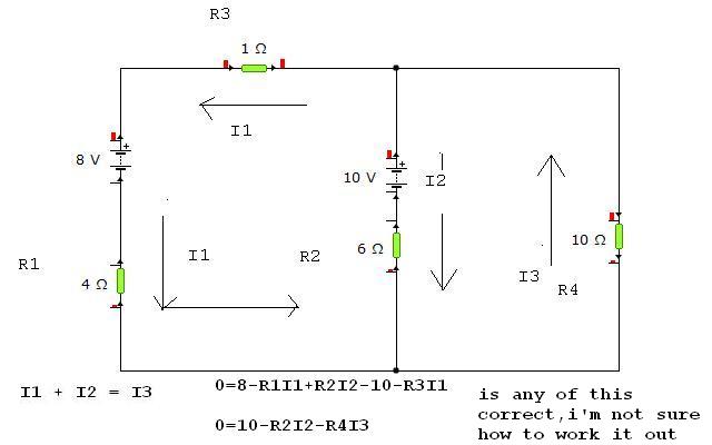
I haven't done this long time, but it looks to me that 0 = 10 - r2*i2 - r4*i3 is the equation where i2 and i3 are defined in opposite direction to those you defined.
The similar problem to the another equation.
I always use the elevation and water flow analogy when considering the voltage level and current.
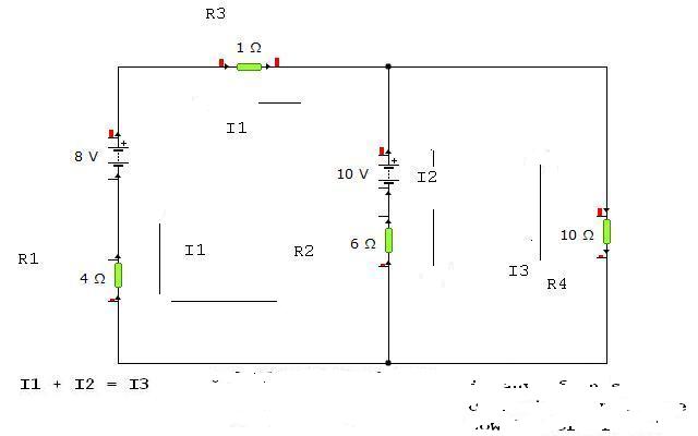
Let's label.
A - i1 and i2 merging point
B - between r2 and 10v battery
C - splitting point of i1 and i2
Going clockwise, starting at A(ground level), you have an uphill climb toward B because i2(water) is comming down from B to A, therefore, B is at elevation +i2*r2.
From B to C, you have a sudden rise by 10v(I call it water tower). So, C is at elevation 10 + i2*r2. Going from C to A through r4 is again another uphill climb since i3 goes from A to C, and it goes up by i3*r4. So, going A -> B -> C -> A, total rise in elevation is 10 + i2*r2 + i3*r4 and it must be 0 because you came back to the starting point which is ground level.
10 + i2*r2 + i3*r4 = 0.
I have never been a fan of "water" analogies. If you work things out as equations and draw the current the wrong way it doesn't matter - the sign of the resultant current when you solve the equations will simply be the opposite of the way you drew it i.e. a negative value. I still think the original equations are correct. That seems to be confirmed by expelleior's solution and a quick simulation by me.
Are you sure about that ?
If i2 and i3 come out as positive number, actual current direction is as defined in the diagram.
DOesn't it make the negative terminal of the 10v battery at the higher potential than positive terminal ?
You are right. If we assume convention current flow from positive to negative then all the currents are really in the opposite direction and the equations should be 0=10 + R2I2 + R4I3 which would then give the result I1=-0.2, I2=-0.5 and I3=-0.7 which means the current is in the opposite direction to that shown.
could you please add image to the post so i can fo9llow better your thinking. itis interesting though i am not yetunderstanding and this current direction thing is where i make mistakes. i would be grateful.
ps. thx LuW
I was using electron current.It shouldnt matter should it so long as you TRAVERSE the circuit the way the direction of chosen current, ?
---------- Post added at 12:47 ---------- Previous post was at 11:57 ----------
If I did use conventional current then I would have traversed and made equations in the opposite direction andmy equations would remain exactly as before so how can it matter ?
It doesn't matter which directions you set the current flow in. You can set the current in whichever directions, but depending on the current direction you set, the equations would be different.
The point to consider is that when the current flows from X to Y, X must be considered to be at the higher potential than Y, and you make equations based on that.
In your original circuit and the current directions you set...
You set I2 flowing from top to bottom, so that upper side of R2 has a higher potential than lower side of it and the difference in potential is I2*R2.
At 10v battery, of course, + terminal always has a higher potential than - terminal and difference in potential is 10v.
For I3 you set to flow from bottom to top, bottom side of R4 has a higher potential than the lower side of it by I3*R4.
Now, you go aound the circuit clockwise on the right in your picture, starting at the bottom of R2, you have I2*R2 rise in potential at R2, 10v rise at battery and I3*R4 rise at R4, which makes total potential rise 10+I2*R2+I3*R4 and of course it must be 0 since it's a closed loop. It makes the equation, 10+I2*R2+I3*R4 = 0.
Changing the picture a little bit, and let's assume you set the I3 direction from top to bottom, and keep everything else the same. Looking at R4, top side of it must have a high potential than the lower side by R4*I3.
Again, going around the circuit clockwise on the right, starting at the bottom, you get a rise by 10+I2*R2 at the R2 and battery, then the potential drops when you pass through R4 by R4*I3. That makes the overall equation, 10+I2*R2 - R4*I3 = 0.
If the current comes out as a positive number, actual current direction is what you set, and if it comes out as a negtive number, the current direction is the opposite to what you set. Both equation above derives the same result EXCEPT I3 from each equation gets the different sign which is because you set the current direction opposite, but that's technically the same result.
This site uses cookies to help personalise content, tailor your experience and to keep you logged in if you register.
By continuing to use this site, you are consenting to our use of cookies.
")