svendsved42
Newbie
I'm a student and would like some help programming an LCD display.
I'm currently working on a project where I'm trying to communicate data to an LCD Displaytech 162B through an PLC Siemens S1200.
I have misunderstood or overlooked something in my software, because nothing is showing on the display.
Hardware:
As mentioned, I'm programming the display with a Siemens S1200 PLC.
Power supply as well as the outputs of the PLC is 24VDC. Each of the outputs from PLC and power supply is voltage divided down to 5VDC (confirmed with voltmeter).
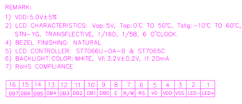
Pin 16: DB7 connected to PLC output as #Data_bit_3
Pin 15: DB6 connected to PLC output as #Data_bit_2
Pin 14: DB5 connected to PLC output as #Data_bit_1
Pin 13: DB4 connected to PLC output as #Data_bit_0
Pin 12: DB3 connected to ground
Pin 11: DB2 connected to ground
Pin 10: DB1 connected to ground
Pin 9: DB0 connected to ground
Pin 8: E connected to PLC output as #EN_1
Pin 7: R/W connected to ground
Pin 6: RS connected to PLC output as #RS
Pin 5: VO connected to potentiometer (potentiometer connected to 5VDC and ground)
Pin 4: VDD connected to 5VDC
Pin 3: VSS connected to ground
Pin 2: LED- connected to ground
Pin 1: LED+ connected to 5VDC
Software:
Is written is Siemens SCL.
Initialization:
Sequence is
Pre-initialization x 3
Pause
4-bit mode - 1 line - 5x7 font.
pause
Display Clear
pause
Return Home
pause
Display on - Cursor off - No blink
pause
Increment - No shift
pause
DDRAM
Timing sequence:

Initialization code:
Sorry the code is so long, but an PLC does not work like a computer, so the timing had to be spelled out and following a timeline.
See comment below
Display data:
So just for simplifying the communication of data I wanted to write the number "9" on the display.
Sequence:
Clear display
pause
Return home
pause
Data
Timing sequence:

Date code:
See comment below
Attached code
I'm currently working on a project where I'm trying to communicate data to an LCD Displaytech 162B through an PLC Siemens S1200.
I have misunderstood or overlooked something in my software, because nothing is showing on the display.
Hardware:
As mentioned, I'm programming the display with a Siemens S1200 PLC.
Power supply as well as the outputs of the PLC is 24VDC. Each of the outputs from PLC and power supply is voltage divided down to 5VDC (confirmed with voltmeter).
Pin 16: DB7 connected to PLC output as #Data_bit_3
Pin 15: DB6 connected to PLC output as #Data_bit_2
Pin 14: DB5 connected to PLC output as #Data_bit_1
Pin 13: DB4 connected to PLC output as #Data_bit_0
Pin 12: DB3 connected to ground
Pin 11: DB2 connected to ground
Pin 10: DB1 connected to ground
Pin 9: DB0 connected to ground
Pin 8: E connected to PLC output as #EN_1
Pin 7: R/W connected to ground
Pin 6: RS connected to PLC output as #RS
Pin 5: VO connected to potentiometer (potentiometer connected to 5VDC and ground)
Pin 4: VDD connected to 5VDC
Pin 3: VSS connected to ground
Pin 2: LED- connected to ground
Pin 1: LED+ connected to 5VDC
Software:
Is written is Siemens SCL.
Initialization:
Sequence is
Pre-initialization x 3
Pause
4-bit mode - 1 line - 5x7 font.
pause
Display Clear
pause
Return Home
pause
Display on - Cursor off - No blink
pause
Increment - No shift
pause
DDRAM
Timing sequence:
Initialization code:
Sorry the code is so long, but an PLC does not work like a computer, so the timing had to be spelled out and following a timeline.
See comment below
Display data:
So just for simplifying the communication of data I wanted to write the number "9" on the display.
Sequence:
Clear display
pause
Return home
pause
Data
Timing sequence:
Date code:
See comment below
--- Updated ---
Attached code
Attachments
Last edited:
")