Continue to Site

Welcome to EDAboard.com

Welcome to our site! EDAboard.com is an international Electronics Discussion Forum focused on EDA software, circuits, schematics, books, theory, papers, asic, pld, 8051, DSP, Network, RF, Analog Design, PCB, Service Manuals... and a whole lot more! To participate you need to register. Registration is free. Click here to register now.

Inverting Preamp schematic

Status
Not open for further replies.

geotFM

Junior Member level 3
Joined
Sep 19, 2017
Messages
29
Helped
0
Reputation
0
Reaction score
0
Trophy points
1
Activity points
276
Hello.This is an inverting preamp i am going to build for audio.Does it look ok?
 

Attachments

  • preamp inv2.jpg
    preamp inv2.jpg
    85.5 KB · Views: 136

Hello.This is an inverting preamp i am going to build for audio.Does it look ok?
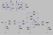
your power supply voltages are too high: 5V max.

R11 may not be necessary, depending on the opamp bias structure. if it IS necessary, its value should be the parallel combination 22K and 10K, not 22K. But the bias current is so low, it all doesn’t matter.
 

The maximum allowed power supply voltage for an OPA2134 is +/-18V so your +/-15V is fine.
Your voltage gain is only 2 times which is only a little more than one.
The input impedance is only 11k ohms.
The high value for C13 passes earthquake frequencies and takes time to charge or discharge.

I agree that R11can be replaced with a piece of wire since the OPA2134 opamps have Jfet inputs with extremely low input current.
 

Why do you think you need C12?

Why do you have two low-pass filters, the input with a ≈800kHz corner, and the feedback with a ≈480kHz corner?
That's way above the audio range.
 

The input R is 11k in // with 47k = 8.9k, which is a little low, R9 could be 220K with same across C4, to give a more defined DC path for the bias current into the inv pin

for an exact gain of 2, R2 = 100k and R10 = 200k ( 2 x 100k in series )

This will lift the input Z to 110k // 100k = 52k.
 

Power supply of +/-15V is fine.I dont know why they say +/-5V max.

Yes input R of about 9.1K is a bit on the low side but i think it is ok for modern equipment.Maybe the 9.1K its not suitable if i used a receiver or a cassete deck of 70s-80s. A more appropriate value would be 47K but going for higher values for R2,R10 would increase noise.Dont know how noticable this would be in reality.

C12 is there just to be safe in case next stage doesnt have a coupling capacitor.It can be ommited.

C13 can be lowered to maybe 4.7uF-10uf? It was choosen to be 22uF so as not to affect a lot the total coupling value including the coupling value of the previous stage.For example if the previous stage had a coupling capacitor of 1uF the total coupling value would be 1uf//22uf =0.95uF. But this combined with the input R of 9.1K gives a roll off frequency of 19Hz.I dont know whether its strict or not.Low pass corner with the values shown for the input cap and feedback cap is around 268KHz.

I have read that if you want to pass 20Hz - 20KHz then the filter corners should be 2Hz - 200KHz

So i have to decide for best values for filter corners,input coupling capacitor,input impedance..
 
Last edited:

Hi,

the big capacitors seem to be polarized. Mind that they will introduce some distortion like a rectifier (surely less).
So if you want to go for low distortion you should not use polarized capacitors. Best are foil or a different circuit concept.

I wouldn´t worry much about noise. While this is not the outstanding low noise voltage OPAMP it is a rather good one. You could use it even with a high gain circuit. With a gain of about 2 it will not be the major source of noise in your system.

Klaus
 

The lowpass filters are needed to remove the AM radio station next door.
The OPA2134 opamps barely work with a +2.5V/-2.5V or +5V/0V supply and the TI sales sheet should have the maximum allowed supply corrected.

What is this "preamp" used for? It has almost no voltage gain and its input impedance is too low to be a buffer.
 

The inverting preamp is part of a tone control.These ae the curves of the tone control without the 6db gain inverting preamp
 

Attachments

  • TC1.jpg
    TC1.jpg
    176.9 KB · Views: 95
  • tc3.jpg
    tc3.jpg
    252.8 KB · Views: 95

The sensitivity of our hearing is logarithmic. Then half the power is -3dB and just a little louder or a little less loud.
Many people cannot hear a 1dB change in loudness.
 
Status
Not open for further replies.

Similar threads

Part and Inventory Search

Welcome to EDABoard.com

Sponsor

Back
Top