arminb73
Junior Member level 3
Anyone who knows a good source of practice using Interrupts on ZedBoard?
I know the brief idea, that the CPU should be busy doing important tasks, and when one of the peripherals sends their interrupt signal it should be paying attention to this peripheral
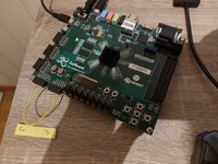
My design looks as so. Connecting sin to sout with a physical wire through the PMOD GPIOs and the interrupt signal to the PS through another physical wire (as seen on second image). My question is now how can I verify that interrupt functionality works ? At what case is it normal to throw a interrupt considering UART data transmission?


I've tried doing this example on my ZedBoard.
But I can't seem to get the same output from the UART-USB input to my computer. I made ext_irq connected to BTNC on the board.

I know the brief idea, that the CPU should be busy doing important tasks, and when one of the peripherals sends their interrupt signal it should be paying attention to this peripheral
My design looks as so. Connecting sin to sout with a physical wire through the PMOD GPIOs and the interrupt signal to the PS through another physical wire (as seen on second image). My question is now how can I verify that interrupt functionality works ? At what case is it normal to throw a interrupt considering UART data transmission?
I've tried doing this example on my ZedBoard.
But I can't seem to get the same output from the UART-USB input to my computer. I made ext_irq connected to BTNC on the board.
Last edited: