Trishool
Full Member level 1
- Joined
- Jul 12, 2001
- Messages
- 97
- Helped
- 1
- Reputation
- 2
- Reaction score
- 0
- Trophy points
- 1,286
- Location
- Himalayas.(mount K2)
- Activity points
- 821
Dear Members;
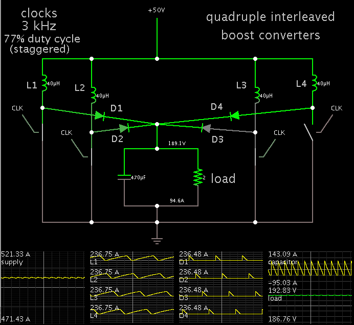
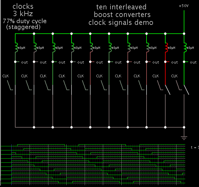
I need to design a DC-DC isolated converter the Dc bus voltage is 50VDC and I want to interleave the current (500Amps) to 10 channels . Then it should be 360/N channels , my question is can we select a longer timeperiod say 720degrees/N . It might sound ridculous.
I also need to clarify , in boost PFC/CCM when we tend to interleave the channels then do we design the system similar to ON/OFF gated at 360/N equivalent timeperiod or do we let the inductor trpezoidal waveform overlap as in the case of 3phse system.
Thanks in Advance...
Regards