Continue to Site

Welcome to EDAboard.com

Welcome to our site! EDAboard.com is an international Electronics Discussion Forum focused on EDA software, circuits, schematics, books, theory, papers, asic, pld, 8051, DSP, Network, RF, Analog Design, PCB, Service Manuals... and a whole lot more! To participate you need to register. Registration is free. Click here to register now.

interfacing coin selector to PIC18F4620

Status
Not open for further replies.

poxkix

Member level 5
Member level 5
Joined
Aug 20, 2011
Messages
87
Helped
0
Reputation
0
Reaction score
0
Trophy points
1,286
Activity points
1,948
The coin selector has no datasheet. So this is totally unknown to me.
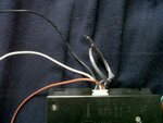
It has 5 wires.
RED - 12v supply
BLACK - ground
GRAY (2) - counter +/-
WHITE - data/signal

My current logic:
The white wire will give a data/signal if a coin has been inserted.

This is the code in detecting the data/signal:
Code:
coin_count = 2;

while(coin_count > 0) {
                            while(PORTA.F0 != 1) {
                                 srand(seed++);
                            }

                                 if(PORTA.F0 == 1) {
                                      coin_count = coin_count - 1;
                                 }
                                      if(coin_count == 1) {
                                           Lcd_Custom_Out(3,13,"05");
                                      }
                       }

These are the things that I already tried to do:
1. connecting the WHITE wire directly to PORTA.F0, what happens the code executes even though there is no coin inserted.
2. I tried inverting the WHITE wire using the 7404, thinking that the WHITE wire gives a default data/signal of 1. It still gives the same result.
3. I tried using a transistor 2222A. Now, the code will not directly execute. If I insert a first coin, it executes but when the second is inserted nothing will happen. (the code should detect 2 coins inserted then it exits)
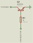
Untitled.png

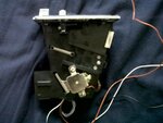
These is what the coin selector looks like:

64765_2959632915984_1416365427_32249354_1095553484_n.jpg431745_2959632155965_1416365427_32249352_1078343268_n.jpg423639_2959631475948_1416365427_32249351_1451380707_n.jpg419703_2959632715979_1416365427_32249353_286094377_n.jpg
 

Hi, I'm not sure but I remember reading somewhere that coin slots send pulses when a coin is received. I think your code should work, but I also think using interrupts is better suited for your purpose of detecting the coins. Also, have you tried if your code works by using a simple switch/button first as your input instead of the coin slot? good luck! :)
 

From your program, i think after one coin inserted it will go exit, because after program writes to LCD than back to top, and porta.f0 still in 1, and then coin_count will decrement once again. Except that high signal is very short, and when the program goes to top, it has been low. But i don't know what's srand(seed++) means, i am not familiar with PIC.

Hi, I'm not sure but I remember reading somewhere that coin slots send pulses when a coin is received. I think your code should work, but I also think using interrupts is better suited for your purpose of detecting the coins. Also, have you tried if your code works by using a simple switch/button first as your input instead of the coin slot? good luck! :)

Yes, you can simulate it with a switch, but you need to add capacitor to eliminate bouncing.
 

Hi, I'm not sure but I remember reading somewhere that coin slots send pulses when a coin is received. I think your code should work, but I also think using interrupts is better suited for your purpose of detecting the coins. Also, have you tried if your code works by using a simple switch/button first as your input instead of the coin slot? good luck! :)

I have simulated it using proteus with a push button and it works well actually. So that's why i'm confused why it won't work in actual. I tried to test the white wire with a multitester, it gives off a constant .37v. If I will insert a coin the value doesn't change. I could have used interrupt but all of my PIC's port pins is already in use.

From your program, i think after one coin inserted it will go exit, because after program writes to LCD than back to top, and porta.f0 still in 1, and then coin_count will decrement once again. Except that high signal is very short, and when the program goes to top, it has been low. But i don't know what's srand(seed++) means, i am not familiar with PIC.
Yes, you can simulate it with a switch, but you need to add capacitor to eliminate bouncing.

Maybe I can put a delay before it goes back to top?
srand is for the rand in mikroC. To generate random values
 

Please try this :

Code:
coin_count = 2;
while(coin_count > 0) {
                            while(PORTA.F0 != 1) {
                                 srand(seed++);
                            }

                                 if(PORTA.F0 == 1) {
                                      coin_count = coin_count - 1;
                                 [B]while(PORTA.F0 == 1);[/B]  //add this line
                                 }
                                      if(coin_count == 1) {
                                           Lcd_Custom_Out(3,13,"05");
                                 }

                       }
 

Please try this :
Code:
coin_count = 2;
while(coin_count > 0) {
                            while(PORTA.F0 != 1) {
                                 srand(seed++);
                            }

                                 if(PORTA.F0 == 1) {
                                      coin_count = coin_count - 1;
                                 [B]while(PORTA.F0 == 1);[/B]  //add this line
                                 }
                                      if(coin_count == 1) {
                                           Lcd_Custom_Out(3,13,"05");
                                 }

                       }

Tried it in the simulation, it worked differently compared to my original. I hope this might fix the problem. I will try this in actual. Thanks. I'll get back with the update
 

Before you start coding for the coin selector, you must find out for sure what output signal is provided by the coin selector when the coin is inserted. One way of this would be to connect a voltmeter at the output and observe output voltage in idle and when coin is inserted. Then, you must try with an oscilloscope to check if output is given in pulses.

Once you find out for sure, what signal is output, then, you won't need to do much trial-and-error and can go on to code specifically as required.

Hope this helps.
Tahmid.
 

Please try this :
Code:
coin_count = 2;
while(coin_count > 0) {
                            while(PORTA.F0 != 1) {
                                 srand(seed++);
                            }

                                 if(PORTA.F0 == 1) {
                                      coin_count = coin_count - 1;
                                 [B]while(PORTA.F0 == 1);[/B]  //add this line
                                 }
                                      if(coin_count == 1) {
                                           Lcd_Custom_Out(3,13,"05");
                                 }

                       }

It didn't work in actual sir.

Before you start coding for the coin selector, you must find out for sure what output signal is provided by the coin selector when the coin is inserted. One way of this would be to connect a voltmeter at the output and observe output voltage in idle and when coin is inserted. Then, you must try with an oscilloscope to check if output is given in pulses.
Once you find out for sure, what signal is output, then, you won't need to do much trial-and-error and can go on to code specifically as required.
Hope this helps.
Tahmid.

I tried it with a volt meter, it gives 0.37v with or without a coin inserted. I don't have any oscilloscope to use.
Assuming it would be a pulse, how or what changes should I make?
 

I tried it with a volt meter, it gives 0.37v with or without a coin inserted. I don't have any oscilloscope to use.
Assuming it would be a pulse, how or what changes should I make?

This is why i said interrupts would be useful if the output of the coin slot was a pulse, use the portb interrupt on change. but you mentioned you used your pic's pins already. you can try using a d-flip flop with its Q-bar output wired to its d input and attach the pulse output of the coin slot (assuming it gives off pulses) to the clock pin of the d-flip flop. connect the Q output of the d-flip flop to the PIC. if you drop a coin, the output of the d-flip will change. program your pic to detect these changes to let it know that a coin was dropped, i.e. use the polling loop to 'sample' the d-flip flop and compare it with the previous sample.
 

Status
Not open for further replies.

Similar threads

Part and Inventory Search

Welcome to EDABoard.com

Sponsor

Back
Top