ansu_s
Junior Member level 3
Hi,
How does integrator phase error affect performance of an integrator? I've read that typically we aim for 1-2 degrees phase error around the frequency of interest, but why?
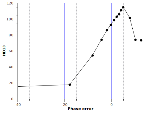
Using a model of a two pole structure (integration pole plus high frequency transconductor pole - ie. a gm-c integrator structure), I looked at the linearity of the integrator over frequency and plotted the phase error (-90 degrees minus the phase shift at that frequency, versus the ratio of first to third harmonic, in db):
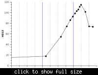
So around 0 degrees phase error (ie. 90 degree integrator phase shift), linearity is better. Is this why we want to minimise phase shift, to improve linearity? But then, looking closely at the plot, linearity is actually highest when phase error is +4 degrees - why does this give greatest linearity and not 0 degrees phase error?
Some have said that reducing phase error affects the Q of the system - but isn't Q how damped the system is? Why does an integrator care about Q? Is this something to do with how lossy the integrator is? If so, wouldn't this affect the DC gain, not the linearity?
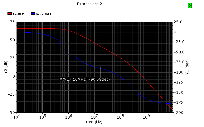
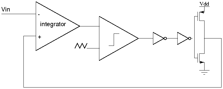
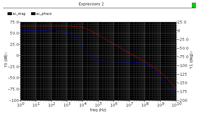
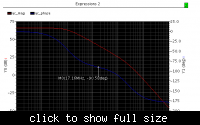
For background: I'm trying to design an integrator for an audio Class-D amplifier, but I'm not sure about how to specify the integrator. Also, if it's important, the magnitude/phase of the integrator is shown below (I just picked the two pole frequencies to give me good a good range of points to investigate effect of phase error on linearity).
How does integrator phase error affect performance of an integrator? I've read that typically we aim for 1-2 degrees phase error around the frequency of interest, but why?
Using a model of a two pole structure (integration pole plus high frequency transconductor pole - ie. a gm-c integrator structure), I looked at the linearity of the integrator over frequency and plotted the phase error (-90 degrees minus the phase shift at that frequency, versus the ratio of first to third harmonic, in db):
So around 0 degrees phase error (ie. 90 degree integrator phase shift), linearity is better. Is this why we want to minimise phase shift, to improve linearity? But then, looking closely at the plot, linearity is actually highest when phase error is +4 degrees - why does this give greatest linearity and not 0 degrees phase error?
Some have said that reducing phase error affects the Q of the system - but isn't Q how damped the system is? Why does an integrator care about Q? Is this something to do with how lossy the integrator is? If so, wouldn't this affect the DC gain, not the linearity?
For background: I'm trying to design an integrator for an audio Class-D amplifier, but I'm not sure about how to specify the integrator. Also, if it's important, the magnitude/phase of the integrator is shown below (I just picked the two pole frequencies to give me good a good range of points to investigate effect of phase error on linearity).