thunderdantheman
Member level 4

G'day All,
Recently I had an in-rush spec added to a design spec from my customer and as usual this was after the hardware design had been approved and manufactured.... typical. Anyway the'yr paying!
In the interim a stand alone circuit is to be used in the prototype.. However I'm having difficulties understanding why my circuit doesn't behave how I expected... clearly my understanding of MOSFETs is hindering me here...
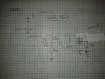
this is what i have...
I'ts a PMOS device SUP53P06 (what i had laying around) and the load I've used simulates the actual load. The reason I've constructed it like this is because I want it inline with the current power switch.. I don't want an additional (or don't have) control signal for the gate.

In the above circuit there is no soft start at all... it looks as thought the MOSFET is hard on from the beginning. and i get a nasty surge.
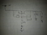
If I use this (see below) more conventional circuit (such as the ones described in a number of app notes)

With the source connected to V+ and switching the load via the gate resistor I get the desired result... However i need the additional control signal to toggle the gate...
Can someone explain why my first method doesn't work like the second? And some ideas how to get a soft start system from when power is first applied?
Thanks.
Recently I had an in-rush spec added to a design spec from my customer and as usual this was after the hardware design had been approved and manufactured.... typical. Anyway the'yr paying!
In the interim a stand alone circuit is to be used in the prototype.. However I'm having difficulties understanding why my circuit doesn't behave how I expected... clearly my understanding of MOSFETs is hindering me here...
this is what i have...
I'ts a PMOS device SUP53P06 (what i had laying around) and the load I've used simulates the actual load. The reason I've constructed it like this is because I want it inline with the current power switch.. I don't want an additional (or don't have) control signal for the gate.

In the above circuit there is no soft start at all... it looks as thought the MOSFET is hard on from the beginning. and i get a nasty surge.
If I use this (see below) more conventional circuit (such as the ones described in a number of app notes)

With the source connected to V+ and switching the load via the gate resistor I get the desired result... However i need the additional control signal to toggle the gate...
Can someone explain why my first method doesn't work like the second? And some ideas how to get a soft start system from when power is first applied?
Thanks.

