Continue to Site

Welcome to EDAboard.com

Welcome to our site! EDAboard.com is an international Electronics Discussion Forum focused on EDA software, circuits, schematics, books, theory, papers, asic, pld, 8051, DSP, Network, RF, Analog Design, PCB, Service Manuals... and a whole lot more! To participate you need to register. Registration is free. Click here to register now.

injection locking at harmonic frequency

Status
Not open for further replies.

Debdut

Full Member level 3
Joined
Oct 29, 2013
Messages
174
Helped
7
Reputation
14
Reaction score
7
Trophy points
1,298
Activity points
2,572
I have a rectangular voltage wave of frequency 1 MHz. I need to frequency multiply it to 6 MHz. Is it possible by injection locking?
If any other method for frequency multiplication is possible, please mention.
I thought of creating a PLL, but the control voltage of the PLL has fluctuations in time domain. So the 6 MHz output I would get through the PLL will not have exactly, 166.666ns period throughout!
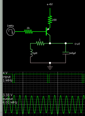
 

Since the 1 MHz pulse is the only instigator you can use as a driver, you won't get exact multiplication. A common technique is to use your 1 MHz pulses to drive a circuit that rings at a higher frequency. Even if it gets a little out of sync after 6 cycles, it is synchronized by each 1 MHz pulse.

Example, LC tank tuned to 6 MHz, receives 'kicks' per 1 Mhz from bias on a PNP transistor.

1884956800_1478712457.png
 

Thank ou for the reply.
I forgot to mention that the inductors should be on-chip.
 

I forgot to mention that the inductors should be on-chip.

Unless you have come up with a ground-breaking method of obtaining high Q inductors in silicon (or, you intend to place high Q wirewounds physically on the chip), your inductors are going to have to be off-chip.
 

Hi,

Why do you think a PLL will not output 166.666ns period time?

Averaged over time there will be about no deviation. It will lock, therefore there can be no long time drift.
Where are your jitter limitations?

Klaus
 

The average period of the PLL output will definitely be 166.666ns. But as you know, there will be control voltage fluctuation at the VCO input due the charge pump and frequency divider nonideality. So the individual periods of the multiplied VCO output will not be 166.666ns, but lower and greater than that in such a way that the average period becomes exactly 166.666ns.
 

Hi,

Yes, I know. This is called jitter. Therefore I asked for your jitter specifications.

Every clock source will jitter. And every clock source will deviate from the desired 166.666ns.
So - in any case you have to live with that. But where are your limits.

Btw: A good designed PLL may output less jitter than the incoming clock source. So it is able to reduce jitter.

Klaus
 

Hi,

Now:
* I twice admitted that there is jitter
* I twice requested your jitter limits
* you refused to give the values
* you refused to accept that all other clock sources have jitter, too.

So how to go on?

Please read some documents and datasheets:
I hope you find some good informations.

https://www.silabs.com/Support Documents/TechnicalDocs/AN513.pdf
www.linear.com/docs/45957
ece.wpi.edu/analog/resources/plljitter.pdf
https://en.wikibooks.org/wiki/Clock_and_Data_Recovery/Noise_is_shaped_by_the_PLL_structure

Klaus
 

Hello Klaus,
Do you think jitter is causing the control voltage variation?
If so, how is jitter manifested in the circuit if the noise is not considered in transient simulation?
After locking, the period of the VCO oscillation at 1000/((N+alpha)fref) time is same as the period at 2000/((N+alpha)fref). Here N and alpha are integer and fractional part of divider modulus.

Sorry, I cannot provide any jitter specifications because I do not have any (I am learning to calculate it). However I know the phase noise characteristics of the standalone VCO. It is about -125 dBc/sqrt(Hz) at 1 MHz offset and -80 dBc/sqrt(Hz) at 10 kHz offset. The VCO oscillation frequency is 400 MHz. Also the loop bandwidth of the PLL is 250 kHz. Note I do not know the phase noise characteristics of the PLL driven-VCO.

Thank you for the links. They were helpful.
 
Last edited:

Hi,

Do you think jitter is causing the control voltage variation?
A PLL is a loop. So here you have the problem to find out where a signal comes from.
If there is a variation, then you should find out if it is a fixed frequency, I assume it is some kind of oscillation, caused by a stability issue.
Therefore one needs to calculate the filter. Especially with a known, fixed input frequency you can improve on low jitter.

Klaus
 

Status
Not open for further replies.

Similar threads

Part and Inventory Search

Welcome to EDABoard.com

Sponsor

Back
Top