Continue to Site

Welcome to EDAboard.com

Welcome to our site! EDAboard.com is an international Electronics Discussion Forum focused on EDA software, circuits, schematics, books, theory, papers, asic, pld, 8051, DSP, Network, RF, Analog Design, PCB, Service Manuals... and a whole lot more! To participate you need to register. Registration is free. Click here to register now.

Inductively detecting an AC Voltage in a Wire

Status
Not open for further replies.

Aggiemundo

Newbie level 5
Joined
Feb 7, 2008
Messages
9
Helped
0
Reputation
0
Reaction score
0
Trophy points
1,281
Activity points
1,371
measure voltage through insulated wire

I'm an AC idiot so I could use some help as I try to better myself. I am trying to build a low cost, low power circuit that will detect when an AC voltage is passing through a set of wires, and then blink an LED to indicate this. I don't want to tap into the AC wires, but want to sense that voltage is flowing through them through induction.

I have taken an unsheilded wall cable hooked to a lamp and coiled a wire around it ten times. My o-scope is showing a nice 4Vpeak AC signal being induced into my wire. However, when I try to pass that through a bridge rectifier (or even a single diode for a half-bridge) I see the same AC wave output as is input to the diode. What am I overlooking here?

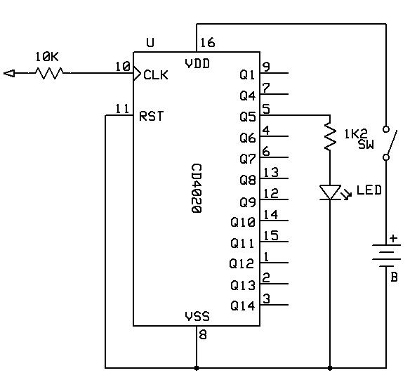
To give you an overview of what I'm trying to do, for the LED flasher I'm just going to use a simple flasher circuit and AA battery as shown here:

**broken link removed**

I believe that if I tie the oscillator circuit into one node of an AND gate, and then tie the other node of the AND gate into my AC current sensing circuit which would be high or low based on an AC current passing through the main wire.

Thanks for any advice (or backhands) you can give!
 

coil around ac cable

Hi,

The link you posted is not working...
I think it's likely that you don't have enough power coming from your coiled wire arrangement to do what you want. You may need a sort of battery powered amplifier used as a buffer before your LED.
Another option would be for you to use a ferrite (for example) core and do a few turns with one of the AC wires and another few turns with your sensing wire, you'll get more flux that way. However, it's more intrusive.

You could also use a simple hall effect current sensor (check out LEM's website) as it would save you a lot of trouble. You could power both sensor and LED from an external battery.
About the fact that you see the voltage after the diode... I think you may want to look into the diode characteristic and get an appropriate load, if possible with your current setup.
Have fun !
 

detect small ac voltages

Aggiemundo,
First, some symantics nit-picking. It is current, not voltage that flows through the wire. Now, on to your question: I believe that the 4V that you see is due to capacitive coupling between the lamp wire and the coil. This would cause a common mode voltage that would appear on both ends of the coil. The voltage would be seen on the scope due to the difference between the scop common and the AC mains common.
.
If you visualize the magnetic field that is induced in the lamp cord due to current flow, the lines of flux appear as circles with the axis of the circles parallel to the lamp wire. Now, if you wind a coil around the lamp wire, the lines of flux are parallel with the windings of the coil. In order to induce a voltage in the coil due to magnetic coupling, the coil needs to be oriented perpendicular to the lamp wire.
.
If you want to measure the current with an inductive device, you need to pass the wire through a core. The core should have another winding into which a voltage proportional to current would appear. The voltage will be proportional to the number of turns on the core and the resistance of the load connected to the winding. Remember, you must pass only 1 wire through the core, otherwise the magnetic fields from the two wires will cancel. This is a current transformer.
Google "current transformer". You will get lots of hits.
.
Another way to detect current is to use a Hall effect sensor. The output voltage will be small, so you would need to amplify it.
Regards,
Kral
 

homemade toroidal current sensor

Hi,
Yes, what Kral told is the key - Capacitive coupling, you do not even need a current in the wire, nor any coil to be put around the AC wire, just take your probe near the AC and extend the mains earth through your body just by touching one end of the probe. Just to get some voltage dropped in the prob, make the prob itself as a small coil and amplify the voltage dropped (not induced) across the coil using a simple high gain FET/FET opamp and drive your LED from there.
Such testers are already available in the market and they are very useful for tracing concealed AC wire routes and for tesing the presence of even grounded Dc voltages and logic levels by single point contact, in this case the body resistance provides the return path for the current.
I have not made a probe of my own, these are only ideas based on the observation of such testers available in the market.
Regards,
Laktronics
 

lem hall effect sensor bangalore

Hello,

no doubt on what's being said about capacitive coupling, also that current can be measured with a current transformer. But it should be noted, that current can be measured also using a toroidal coil without a core. As a particular advantage of this technique, the coil can be opened and closed around a conductor to be measured. Although it isn't very sensitive for low frequencies, it is rather simple to apply and well fitted for home-made instruments to my opinion.

Regards,
Frank

www.pemuk.com
 

inductive current sensor

Thanks for all the responses guys. This is definately a lot of help.

So I went and got a toroidal ferrite core and wound my sensing wire around it (it now looks like a standard toroidal inductor). I put one of the AC wires through the center of the toroidal core to the lightbulb and turned the bulb on. Again, I see a sine wave on the scope (smaller amplitude this time).

I assumed if I put a diode between the two ends of my sensing wire I would see only the positive side of my sine wave showing up as the negative was clipped out. However, I'm seeing the same result of the exact same signal on the cathode of the diode as is going into the anode. I'm still confused. What am I doing wrong?

Thanks in advance!

Added after 2 minutes:

Also, here is the correct link for my LED blinking circuit. I'm going to hook the output of the AND gate to the second column of inverters. One input of the AND gate will be supplied by the oscillator circuit, and the other input will be supplied by this current sensing circuit thats giving me fits!

http://www.discovercircuits.com/H-Corner/led-flasher.htm
 

detecting ac in a wire

Hello,

regarding the diode experiment, I wonder how you connected your oscilloscope to the current transformer? Where did you connect the probe's ground wire? The two probe terminals should be connected to both ends of the sensing wire to measure the voltage induced in the transformer. It also could be, that the used core hasn't enough permeability (µr) for a current transformer. If it's a core used for filter chokes, it's probably low permeability.

You should define a current threshold for your indicator, in terms of wattage or current flow.

Regards,
Frank
 

detect small ac voltage


This is simple LED blinking AC voltage detector. LED will blink when voltage is present in wire when insulation is touched or close to it even if there is no current flowing.
 

scope ac voltage

So do you think it would work if I went with a large off the shelf toroidal inductor that had a center opening large enough to run one of the wires through?

Added after 1 hours 20 minutes:

Sinisa,

I'm having a hard time seeing how your circuit works. Is that 10k resistor on the clock input connected to a wire that will go close to the AC wire? Can you explain a little about how this would work? Thanks so much!
 

homemade current sensor using ferrite core

Dear Aggiemundo,

Lot about your problem is already been said, what i would like to add is did you check with the specs of your diode that you are using? Imean the power ratings and the threshold voltage? A half wave rectifier is able to Rectify only when the reverse voltage is within the Vcutoff.

I guess ur diode's specs needs a re-check.

Sai
 

I don't think its the diodes. I think everyone has hit it on the head that the voltage I'm seeing is just a capacitive coupling between the two wires and no real current is flowing through my wire. I think the same has been the case when I'm using the toroidal core with wire wound around it.

I just can't help but thinking this shouldn't be that hard. Any further advice or ideas on how to implement such a circuit are really appreciated, because right now I'm beating my head up against a wall! Thanks!
 

Aggiemundo said:
So do you think it would work if I went with a large off the shelf toroidal inductor that had a center opening large enough to run one of the wires through?

Added after 1 hours 20 minutes:

Sinisa,

I'm having a hard time seeing how your circuit works. Is that 10k resistor on the clock input connected to a wire that will go close to the AC wire? Can you explain a little about how this would work? Thanks so much!

unconnected side or 10K resistors is connected to probe (piece of insulated wire) that couples to your cable capacitively. High impedance of counter input insures that even that small current is enough to trigger counter input. You might have to experiment with size and shape of probe and maybe adding yourself as ground to - of battery when you hold detector.
10K resistor has two purposes: it limits current that might pass through internal protection diodes in counter due to ESD and limits bandwidth of input by forming RC filter with input capacitance. If you find counter too sensitive you could increase this resistance and other way arround.
 

Status
Not open for further replies.

Part and Inventory Search

Welcome to EDABoard.com

Sponsor

Back
Top