Continue to Site

Welcome to EDAboard.com

Welcome to our site! EDAboard.com is an international Electronics Discussion Forum focused on EDA software, circuits, schematics, books, theory, papers, asic, pld, 8051, DSP, Network, RF, Analog Design, PCB, Service Manuals... and a whole lot more! To participate you need to register. Registration is free. Click here to register now.

Increasing gain in low voltage, low current dynamic mic preamplifier

Status
Not open for further replies.

neazoi

Advanced Member level 6
Joined
Jan 5, 2008
Messages
4,123
Helped
13
Reputation
26
Reaction score
15
Trophy points
1,318
Location
Greece
Activity points
36,955
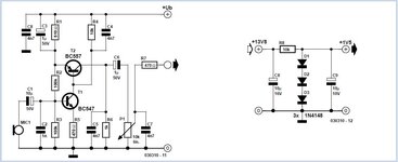
I have found this low voltage, low current dynamic mic preamplifier
which I built and it works fine.

My SSB transceiver, where the preamplifier is fit in, has a "phantom power" to the preamplifier. That is only 2 cables and it passes audio in the power line, that is the way it is designed.
Problem is that this can supply low current, so any attempt to draw more current from it, drops the voltage (starting from 6v unloaded).
This preamplifier dropped the voltage to about 2v and worked fine.
But I need a little bit more gain out of it, so I do not have to shout on the microphone for full transceiver power output.
How can I get more gain out of this circuit, what modifications can I do, always having in mind the low voltage low current situation?
 

Attachments

  • Simple-Microphone-Preamplifier-Schematic-Circuit-Diagram.jpg
    Simple-Microphone-Preamplifier-Schematic-Circuit-Diagram.jpg
    41.6 KB · Views: 185

it's not a very good ckt as the pull down for the neg output half cycles is the 1K resistor R6

choose a whole new and better two transistor amplifier ...
 

it's not a very good ckt as the pull down for the neg output half cycles is the 1K resistor R6

choose a whole new and better two transistor amplifier ...
How about altering R4 or R6?
 

A low noise single stage IC can give more gain with no more current consumption. The problem with the schematic shown is it has no feedback, it already runs flat out. If you increase the resistor values you might squeeze a little more gain from it but at the expense of it all being lost as it drives the load.

If you need more phantom power, the best way to do it is at source, make more current available.

Brian.
 

    neazoi

    Points: 2
    Helpful Answer Positive Rating
A low noise single stage IC can give more gain with no more current consumption. The problem with the schematic shown is it has no feedback, it already runs flat out. If you increase the resistor values you might squeeze a little more gain from it but at the expense of it all being lost as it drives the load.

If you need more phantom power, the best way to do it is at source, make more current available.

Brian.
Can you suggest such an IC circuit Brian? Remember, this can go as low as 2v or even 1.5v if loaded enough.
I will try increasing R4 and R6 by a factor of 5 and see what happens.
Another thing that I could do, is find another dynamic capsule. The one I am using now is taken from an old telephone (it is dynamic, checked) and it might not have that much gain.
 

I think before speculating about low voltage amplifiers you need to find out how much current is really available. I'm not sure what is 'behind' the microphone input inside your transceiver but it may be nothing more than a 'pull-up' resistor to provide a weak current source. If it is, you can probably dispense with the amplifier completely and use an electret mic instead, they already have a built in FET amplifier and produce many times more signal level than a dynamic insert.

What is the transceiver? can you show us the schematic at the mic input?

Brian.
 

    neazoi

    Points: 2
    Helpful Answer Positive Rating
I think before speculating about low voltage amplifiers you need to find out how much current is really available. I'm not sure what is 'behind' the microphone input inside your transceiver but it may be nothing more than a 'pull-up' resistor to provide a weak current source. If it is, you can probably dispense with the amplifier completely and use an electret mic instead, they already have a built in FET amplifier and produce many times more signal level than a dynamic insert.

What is the transceiver? can you show us the schematic at the mic input?

Brian.
I am afraid I can't. It do not have the schematic and no one seems to have this. It is a Greek transceiver produced back in the 80s, the model GCR250 from a small company back then, called Wide Spectrum. This is based on a Racal tactical radio, with selectors and divider to set the frequency (amazingly stable for the time).

By reverse engineering, I found, there is a 2.2k resistor inside the transceiver that provides the power (and probably limits the current, but it might not be only this one to do so) to the microphone circuit. Through this resistor, audio is also passed (bad technique).
The hand microphone has only 2 cables.
The ground is common.
The power/audio connection, is fed through the PTT switch to the circuit, to power it up and to pass the audio to the transceiver.

The initial microphone had an electret, which worked in a bit greater sensitivity, but yet not enough to peak nicely and I had to shout on the mic.
I thought that I could a bit preamplify this, so I tried a simgle BJT preamp but this did not work ok.

Then I found this circuit shown to you, which seems to work, but the gain from the dynamic mic is less than with the electret alone.

I have 2 ideas:

1. Short this R5, to increase gain.
2. Using an electret (with it's resistor) in place of the dynamic capsule and leave the rest of the preamp as it is.

What do you think?
 

Temperature in my office is currently 38.94C and climbing so forgive me if I type nonsense!

You could try the electret instead of the dynamic mic but I suspect the supply voltage available to it would be too low. Typically they draw about 0.5mA with a 5V supply but I would guess they stop working when the voltage drops much below that.

Try this test:
1. check the mic supply with nothing at all connected to find the 'no load' voltage, this will probably be the actual supply as nothing will be dropped across the load resistor.
2. Do the same with a 10K resistor across the mic input and measure the voltage.
3. Do the same with a 1K resistor and measure the voltage.

From that it should be possible to see if there is constant current source or simply a resistor from a constant voltage.

Brian.
 

    neazoi

    Points: 2
    Helpful Answer Positive Rating
Temperature in my office is currently 38.94C and climbing so forgive me if I type nonsense!

You could try the electret instead of the dynamic mic but I suspect the supply voltage available to it would be too low. Typically they draw about 0.5mA with a 5V supply but I would guess they stop working when the voltage drops much below that.

Try this test:
1. check the mic supply with nothing at all connected to find the 'no load' voltage, this will probably be the actual supply as nothing will be dropped across the load resistor.
2. Do the same with a 10K resistor across the mic input and measure the voltage.
3. Do the same with a 1K resistor and measure the voltage.

From that it should be possible to see if there is constant current source or simply a resistor from a constant voltage.

Brian.
39C in UK!?!
It seems the earth has moved 90 degrees!

I will do the test you mention.

I have the feeling that an electret there will solve the problem, unless the circuit does not provide any gain and fools me.
 
Last edited:
Status
Not open for further replies.

Similar threads

Part and Inventory Search

Welcome to EDABoard.com

Sponsor

Back
Top