Continue to Site

Welcome to EDAboard.com

Welcome to our site! EDAboard.com is an international Electronics Discussion Forum focused on EDA software, circuits, schematics, books, theory, papers, asic, pld, 8051, DSP, Network, RF, Analog Design, PCB, Service Manuals... and a whole lot more! To participate you need to register. Registration is free. Click here to register now.

[SOLVED] INA126: getting unexpected results

Status
Not open for further replies.

denujith

Member level 5
Member level 5
Joined
Oct 5, 2010
Messages
85
Helped
6
Reputation
12
Reaction score
6
Trophy points
1,288
Activity points
1,886
Hi All,

I am building a thermometer interfacing a S-type thermocouple. Planning to use INA126 operational amplifier to amplify thermocouple output.

I assembled the circuit in a bred board and tested.
Here are my test results:

Code:
Rg/Ω = 258

In/mV		Out/V
-----------------------
0		1.76
1		1.93
2		2.13
3		2.31
4		2.48
5		2.70
6		2.90
7		3.09
8		3.25
9		3.44
10		3.65
11		3.83
12		4.02
13		4.22
14		4.42
15		4.58

A voltage divider was used to generate input voltage in the range of miliivolts.

According to the datasheet, Gain:

G = 5 + 80kΩ/Rg

But my test results doesn't give me the theoretical Gain as specified in the datasheet. Then I removed the Rg and applied 1mV to the input. It produced fluctuating value in between 0.8V and 1.1V.

My hardware setup is as below:
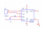
INA126.PNG

Please let me know what can be the reason to deviate Gain from the intended values as mentioned in the spec.

Regards,
/Lakmal
 
Last edited:

To make the amplifier work correctly, you have to apply suitable supply voltages and assure, that Vin is in the specified common mode voltage range (TC must not float). The schematic doesn't clarify, if these conditions are met.
 
Hi FvM,

I used ±12V as the supply and used a voltage divider as the input (sourced from output of 7805 regulator).

Code:
       +5V
       |
       /
       \
       /
       \<--------------> to pin 3
       /
       \
       /
       |
       0V

/Lakmal
 

It was because of TC is floating and induced voltages in the input terminals due to EM.
Lakmal
 

Hi,

I implemented the circuit using a PCB and my test setup is as follows.
ina126.jpg
I adjusted R so that it gives a 13mV and Rg to give 270 gain. PIC [with AD converter and 7-segment display] is fed from Vout and I see that the output swings, . i.e. ~±0.2V as seen by the PIC.

Can you please let me know what can be the reason for swinging of output of INA126 for a "steady" [I am using a 6V Lead-Acid battery] 13mV input?

Note:
This circuit is to interface a Thermocouple to a PIC. At this moment I don't have access to a Thermocouple. I am using the voltage divider for this.

Regards,
/Lakmal
 
  • Like
Reactions: dselec

    dselec

    Points: 2
    Helpful Answer Positive Rating
You may like to connect the 10K resistor between the circuit ground and the negative node of the loop at the most left (the node that connects the 6V battery minus terminal and the lower terminal of the potentiometer R).

Kerim
 
Last edited:

I did that already and it didn't work. Can it be a problem with the PCB design?

Note:
Input is in the range 0 <-> 15 mV

Lakmal
 
Last edited:

I did that already and it didn't work. Can it be a problem with the PCB design?

Note:
Input is in the range 0 <-> 15 mV

Lakmal

You are right to be confused, the circuit is simple and clear.
As long your input signal is in series in the loop formed by IN+, IN- and ground, the IC should give an output Gain*Vin (positive in our case here).

Did you tests other ICs? If all give the same result, then there is surely, as you said, a difference between the circuit schematic and the actual PCB layout.

I believe soon you will see this difference (friendly advice: check the PCB, or anything else, as if it were the work of someone else and you look seriously to tease him by finding his mistake. :smile: Personally, my final check of any of my works is done this way. This started since I was a student when checking the answers I wrote for an exam :wink: )
 

I assembled the circuit on a bred board and now the output swinging has been reduced [from ±100 to ±20, but not eliminated]. I think it must be a problem with the PCB design and I am looking into it now. Can you please let me know any place where I can get these 'PCB tips' so that I won't go wrong next time? Thank you for your concern and your advice.

Lakmal
 

Here is the PCB I designed. This is the latest design I made and about to etch. Can you please let me know is there anything 'wrong' you see here?
ina126_PCB.jpg

Lakmal
 

It is not like the one shown on post #5. Do you follow a new schematic?
For example, there are 5 nodes (pins or terminals) connected to ground on your first circuit. On your PCB there are only 3.

Kerim

Edited:
I usually draw the circuit and then draw its PCB using a free program called 'Kicad'. There is a friendly Yahoo group for support. Using such a program, the components and their connections are transferred to the PCB window. So missing a component or a track while drawing the PCB layout is practically eliminated.
 
Last edited:

I assembled the circuit on a bred board and now the output swinging has been reduced [from ±100 to ±20, but not eliminated].
You previously reported +/- 0.2 V, by the way....
Anyway, how do you measure the "swinging". Assuming you are using an oscilloscope, what's the waveform?
I think it must be a problem with the PCB design
The latest results are with a breadboard or PCB? What did you connect at the input? Did you try a simple input short? Did you verify the Rg resistance value, if it's represented by variable resistor.
It is not like the one shown on post #5. Do you follow a new schematic? For example, there are 5 nodes (pins or terminals) connected to ground on your first circuit. On your PCB there are only 3.
I only count a difference of one, the missing ground connection of negative input.
 

I only count a difference of one, the missing ground connection of negative input.

I forgot to put my glasses. :oops:
You are right only pin 2 is not connected to ground as on the circuit (post #5).

Added:
I think he follows another circuit... the real/final one. On post #5, it was just a test circuit.
 

I was away for sometime and started back with the project. Still I am having difficulties. I connected type-K thermocouple to input terminals. But the display stays at a fixed number. I measured the INA126 output and it seems it doesn't amplify the input. Output stays at .556V all the time. I have attached the schematic and the PCB I used.

Can you please let me know what can be the reason? I will attach my source file as well.
 

Attachments

  • PCB2.GIF
    PCB2.GIF
    21.5 KB · Views: 117
  • schematic.GIF
    schematic.GIF
    34.5 KB · Views: 142
  • main.rar
    1.8 KB · Views: 96
  • Like
Reactions: dselec

    dselec

    Points: 2
    Helpful Answer Positive Rating
look at this link and tell how you thermo..is connected
checkout page 8-9...why is your ref to an...grounded
and remember your reading should reads your surrounding temp ..say 25c but your citcuit will show zero thats why u need ref to tell the circuit its 25°c deg°.
S-type thermocouple
https://www.ti.com/lit/ds/symlink/ina126.pdf
about post #5 recheck u connected the minus from batt to grd that's the only thing missing there.
 
Last edited:

The schematic doesn't clarify if the TC has a ground connection to assure correct common mode voltage. You know this has been a problem last year. Besides this point, I don't see a reason why the amplifier should not work.
 

"this has been a problem last year" ???
tc common ground ??? denu.. willneed to be more accurate.
 

@FvM: You guided me through this (and I am very much thankful for that) and unfortunately before getting it solved I had to move on to something else for a very long time. I came back to the project couple of days ago.

I just obtained the thermocouple from the lab and it has two leads (red, black) with a shield. I connected the shield to the circuit ground.

@dselec: Yes, I haven't provided a path for input bias current return. Can this be the problem?

I am wondering whether have I put the ground correctly. Should the Vss of PIC and Vss of INA126 should be connected? I mean INA126 needs separate ground connection. I have connected PIC's Vss to INA126's ground.

schematic_2.GIF

Thanks
 

Make sure your tc shield pin 1 is not connected to +/- of tc pins 2-3
checkout the an.. layout and application ..read POST #15
ITS NOT A BIAS its room temp ref ...if u dont use it u will get zero deg temp even if u r right now in the north-pole outside in the snow with -40 deg or insainai dessert +40deg .
all grounds tied together.
post#5 must work remember connect _batt to grd.
what are your voltages measure them and post.
 

@dselec: Thank you for your input. But room temp may not be used in this case as I have a different strategy to convert thermo voltage to temperature. This is for a furnace and will be used in this furnace only. I already have readings of Voltage (type-s) vs Temperature (actual temperature of the furnace). I have a look up table to convert V to T.

I'll check the thermocouple terminals whether are they connected to shield.
 

Status
Not open for further replies.

Part and Inventory Search

Welcome to EDABoard.com

Sponsor

Back
Top