Continue to Site

Welcome to EDAboard.com

Welcome to our site! EDAboard.com is an international Electronics Discussion Forum focused on EDA software, circuits, schematics, books, theory, papers, asic, pld, 8051, DSP, Network, RF, Analog Design, PCB, Service Manuals... and a whole lot more! To participate you need to register. Registration is free. Click here to register now.

Importing verilog netlist to Cadence

Status
Not open for further replies.

jkbagada

Newbie level 6
Joined
Aug 14, 2010
Messages
11
Helped
0
Reputation
0
Reaction score
0
Trophy points
1,281
Location
india
Activity points
1,361
Hello friends

I have imported a synthesized Verilog netlist to Cadence for spice simulations. Now i see there are no VCC, GND pins at top level. while down at standard cell level VCC, GND pins can be seen. I tried running simulations by giving stimuli in ADE at Global sources but shows errors, moreover i dont wish to give supply by stimuli.

How do i give supply (by connecting voltage source) at the top most hierarchy?

Thank you!
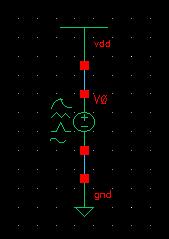
 

Hi!
At the top level add vdd, vsource and gnd from analogLib library (see the pic). Specify in vsource the voltage you need...

41_1329482737.jpg
 

Hi ,Thank you


This could be done but the pins at lower hierarchy (standard cell) are named VCC! and GND!, you think this will directly connect the source to those pins since global pins are named Vdd and gnd?.
 

Pin names for vddand gnd you can see in properties window, for vdd is vdd! and for gnd is gnd!.
In our standart library std cells the power and ground pins are vdd! and gnd!, so there are no problems...
Sorry, but I don't know how to handle power ground pins in your case.
 

Status
Not open for further replies.

Part and Inventory Search

Welcome to EDABoard.com

Sponsor

Back
Top