Bobson2000
Junior Member level 2
Hi, i'm trying to do impedance matching of small piece of RF path.
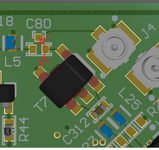
Target impedance is 50Ohm. I'm measuring it by VNA (calibrated, S11, Smith chart) connected port 1 to UFL connector (J4), from which path goes by 1nF capacitor (DC-block) to RF balun (impedance matching for mixer circut). First graphics shows layout, secons shows schematic. Traces (width, prepreg heigth) on PCB are calculated for about 50Ohm. Device is suppiled, and mixer circut is enabled when measerement is performed.
So, first measurement shows impedance 22,3,+3,7j. So i use will-kesley calculator which shows that i need just add series resistor about 27Ohm - so i added it, and impedance goes lower, not higher - i tried to add it after, befor, and instead of capacitor. In will-kesley calc first i set Z = 22 + 3.5j (meabe thats wrong way) and add series resistor. So i tried to make matching instinctively: i added a capacitor in series, and resistor i parallel as graphic shows, and after several tries, i found quite well values: 27pF, and 56Ohm, that gives impedance (measured) 49+20,35j.
1.Can somebody explain me whats going on? Its my almost first time with impedance matchning. Meabe these small piece of path have no siginifcant impact on whole RF path, meabe the shapes of pads vs. shapes of traces are make me this jokes, meabe i do measurement in wrong way? I tried the same method on another (different) piece of RF path, and impedance changes not according to what the calculator and manual calculations indicate.
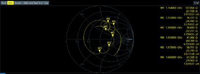
2.Second question is about impedance matching for two bands - third graphics - i want to move M5 and M2 points near middle of chart - is it possible by adding components?
I would be very grateful for any help.
Best regards
[EDIT] Meabe my method, or thinking is wrong, because substantially finaly the J4 (is just added for measurement, or input external signal) will be not used, and capacitor will be placed from L5 to balun (T7).
Target impedance is 50Ohm. I'm measuring it by VNA (calibrated, S11, Smith chart) connected port 1 to UFL connector (J4), from which path goes by 1nF capacitor (DC-block) to RF balun (impedance matching for mixer circut). First graphics shows layout, secons shows schematic. Traces (width, prepreg heigth) on PCB are calculated for about 50Ohm. Device is suppiled, and mixer circut is enabled when measerement is performed.
So, first measurement shows impedance 22,3,+3,7j. So i use will-kesley calculator which shows that i need just add series resistor about 27Ohm - so i added it, and impedance goes lower, not higher - i tried to add it after, befor, and instead of capacitor. In will-kesley calc first i set Z = 22 + 3.5j (meabe thats wrong way) and add series resistor. So i tried to make matching instinctively: i added a capacitor in series, and resistor i parallel as graphic shows, and after several tries, i found quite well values: 27pF, and 56Ohm, that gives impedance (measured) 49+20,35j.
1.Can somebody explain me whats going on? Its my almost first time with impedance matchning. Meabe these small piece of path have no siginifcant impact on whole RF path, meabe the shapes of pads vs. shapes of traces are make me this jokes, meabe i do measurement in wrong way? I tried the same method on another (different) piece of RF path, and impedance changes not according to what the calculator and manual calculations indicate.
2.Second question is about impedance matching for two bands - third graphics - i want to move M5 and M2 points near middle of chart - is it possible by adding components?
I would be very grateful for any help.
Best regards
--- Updated ---
[EDIT] Meabe my method, or thinking is wrong, because substantially finaly the J4 (is just added for measurement, or input external signal) will be not used, and capacitor will be placed from L5 to balun (T7).
Attachments
Last edited:


