Continue to Site

Welcome to EDAboard.com

Welcome to our site! EDAboard.com is an international Electronics Discussion Forum focused on EDA software, circuits, schematics, books, theory, papers, asic, pld, 8051, DSP, Network, RF, Analog Design, PCB, Service Manuals... and a whole lot more! To participate you need to register. Registration is free. Click here to register now.

IGBT switching loss control

Status
Not open for further replies.
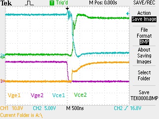
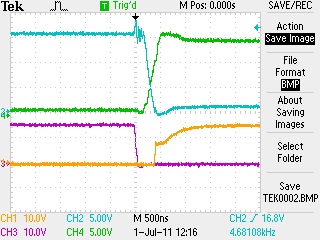
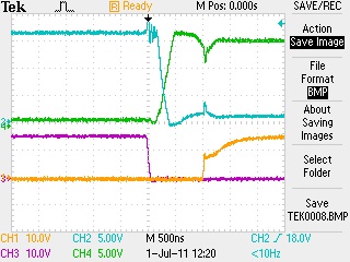
Here are the simultaneous waveforms I'm talking about:
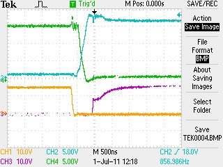
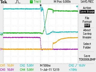
The dead times are 200ns,400ns,600ns,800ns,1000ns at gates but it is not seen at collector voltages.
Yellow and purple are low side gate voltages, blue and green are collector voltages respectively.
46_1309526636.jpg
20_1309526636.jpg
44_1309526636.jpg
97_1309526636.jpg
42_1309526636.jpg
 

I can't have dead time at collector voltages
The voltage waveforms are constituted by both transistor and diode operation. In a bridge output with inductive load, the commutation timing is depending on the output current sign. In "active" quadrant, output voltage and current have equal sign, the output is commutating immediately on transistor turn-off and the current transferred to the opposite diode. In "passive" quadrant, output voltage and current have opposite sign, the output is commutating from the diode to the transistor on-turn on.

Your waveforms are operating in an active quadrant, so the output voltage is always changing on turn-off.
 
Last edited:

FVM is correct; with an inductive load, the diodes will conduct the load current during dead time, causing the bridge output to appear to be "driven." Turning the IGBTs on won't actually do anything until the load current changes sign completely.

It doesn't look like the nasty waveforms are there in those pictures, at least not on the gates.
 

In these last waveforms I changed the unstable piezoelectric load with resistance (not pure but close, Z = 43ohms = 41+j13 ohms @ 25khz) capable of handling high currents. That's why the waveforms are better. Before driving that unstable resistive+capacitive load I think I should solve my other problems. So does diodes also conduct while the circuit has resistive load? Is there a document which discribes that event, I didn't get it yet.

Is it bad to be in active quadrant? I mean does the intersection area of the Vce's cause any shoot through or unwanted switching loss? I am confused.
 
Last edited:

In these last waveforms I changed the unstable piezoelectric load with resistance (not pure but close, Z = 43ohms = 41+j13 ohms @ 25khz) capable of handling high currents.
So you were driving a resistive load, but still through the transformer, right?
That's why the waveforms are better. Before driving that unstable resistive+capacitive load I think I should solve my other problems. So does diodes also conduct while the circuit has resistive load?
Ideally no, a resistive load won't conduct during the dead time. But your transformer's magnetizing inductance will make it look slightly inductive. That last set of waveforms looks pretty typical (though I think the turn on time is too slow, and the dead time is probably excessive).
Is it bad to be in active quadrant? I mean does the intersection area of the Vce's cause any shoot through or unwanted switching loss? I am confused.
Shoot through is an independent problem from your load impedance or quadrants or whatever. Shoot through should be solved just by adding dead time to the gate drive. In a good circuit, the gate waveforms should not be affected significantly by the load characteristics. At most you should see slower rise and fall times when operating at higher load current. But if your gate waveform starts seriously distorting or oscillating when you change the load, then something is wrong with the drive circuit and needs to be fixed.
 

300nS looks like a good medium value for the dead time - the switching looks to be normal and OK with no shoot thru (certainly the lower gate drive signals look fine) I think we need to look atthe details of your load to go further - Regards, Orson Cart.
 

Is it bad to be in active quadrant? I mean does the intersection area of the Vce's cause any shoot through or unwanted switching loss?
There nothing like good or bad in this regard. Load current waveforms are just an application condition to be considered and usually can't be changed at will. My point was to explain what's going on, I don't see anything dubios in the latest waveforms. You have to assure, that both bridge transistors can't turn on simulataneously, that seems no problem at present.

What you call "intersection area of Vce's" is just another word for the fact that both voltages aren't independent of each other, but (should) sum to Vbus. When you see a ringing in one Vce waveform that's missing in the other, you can conclude that either the measurement is incorrect, e.g. picking up interferences, or Vbus itself is actually ringing, which may be understood as insufficient bypassing.
 

I neither have the transformer nor the capacitor in those waveforms, just the resistive load.
A pure resistive load won't cause the output current to commutate to the diode on it's own. There must be at least some circuit inductance to get the shown waveforms.
 

I revealed the impedance of the resistive load before. Surely, the rest of the board has also some inductance effect too, as nothing is purely resistive in nature. Do you think this inductive effect is higher than usual?

I want to test the circuit with this resistive load while draining 5A current at 220V and monitor the temprature rise on IGBT cooler. I want to be sure of how much temprature rise should I see on my passive cooler in this normal condition as you both agreed.

Is there any clear document you can reference, explainig power loss & temprature rise on cooler relation?
 

I changed the IGBT's back to faster ones (in post #1) and added external recovery diodes too (in post #40). I used only flange resistance heater as load. In this configuration I applied 220V and 8A. The performance of the circuit seems very good. There is no overheating problem.

And after that I changed the configuration. I applied transformer as load to the circuit. I connected the flange resistance heater to the secondary winding. I both drived the circuit with and without series capacitor to the primary of the transformer. I see that when I connect 330nf series capacitor to the primary, I get the most power out of it. I think that's the match of leakage inductance of my transformer at 25khz.

Now I am going to try to drive the unstable piezoelectrics again. I am going to connect it to the secondary of the transformer as usual but will add series inductor to compansate its capacitive effect. I'll post the results soon.
 

330nF and 25kHz gives 122uH for the total leakage - which seems high - do you have a picture of your transformer? Given the likely low value of the piezo capacitance you will need to retune the C on the primary side and experiment with the L on the sec side - ideally you want the 25kHz to be slightly above the res freq of the load to avoid hard switching of the diodes across the igbt's - Regards, Orson Cart.
 

How can I calculate or measure leakage inductance? I read some document saying short the secondaries of the transformer and measure the inductance of the primary. That's the leakage inductance, is it true? ... I wound the transformer ourself (hand winding) , winding with litz wire to a E65x27 ferrit core.


The photo clarifies, that the transformer has an air gap, so the main inductance surely can't be neglected in the measurement. You should perform inductance measurements with open and short secondary to determine both leakage and main inductance.

The main inductance can be also estimated from core data, number of windings and actual air gap.
 

OK, the air gap will give a much lower magnetising L for the Tx, and it is this giving you some extra currents in the igbt's at turn off - worth trying the system without the gap in the Tx - you will need a DC blocking cap though (unless you are using current mode control) say 10uF, 250VDC, in series with the Tx, then you are free to tune the load with extra L's as required. Regards, Orson Cart.
 

Status
Not open for further replies.

Similar threads

Part and Inventory Search

Welcome to EDABoard.com

Sponsor

Back
Top